Rigid bodies are all collision objects as soon as they come in contact with one other. This is a little different from other simulations in Softimage (soft body, cloth, and hair) where you need to specifically set up an obstacle object to create a collision. For example, to animate billiard balls colliding with each other, you simply make the balls into rigid bodies. Then when they come in contact with each other, they all react to the collision.
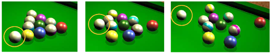
All billiard balls are assigned as active rigid bodies, so when the white ball (circled) hits them, they all react to the collision.
At least one rigid body must be active to create a collision. When you have collisions between two or more active objects, they all move because they are all affected by the dynamics.
If you want to create an obstacle that doesn't move (not affected by dynamics), it must be a passive rigid body. For example, if you want to animate a billiard ball bouncing against the edges of a pool table, make the ball an active rigid body and the table a passive rigid body. As soon as the ball comes in contact with the table edge, the ball rebounds off it but the table doesn't move. For more information on active and passive rigid bodies, see Active or Passive?.
All rigid bodies use a set of collision properties to calculate their reactions to each other during a collision. These properties include elasticity, friction, and the collision geometry type (the geometry used during the calculation of the collision).
To keep the relationships simple with collisions, it's usually best to set the values for only one rigid body at a time. For example, if you have many active rigid bodies bouncing off a passive one, you could set the collision properties for only the passive one. This way you can maintain the passive rigid body's parameters as a constant. Then if you want each active rigid body to react differently to the passive one, you can set each of those separately after you've established the base collision properties of the passive rigid body.
Select two or more rigid bodies with at least one of them being active.
Make sure that the geometries of the objects come into contact with each other (their geometries interpenetrate at some point).
For best results, you should set up the rigid bodies so that their geometries don't interpenetrate at the first frame (initial state) of the simulation.
Set the collision properties for all of the rigid bodies in their Rigid Body Properties editor as described in this section.
Play the simulation to have the rigid bodies collide.
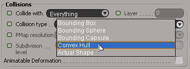
During rigid body collisions, you can set the type of geometry to be used for each rigid body only for the collision. This geometry can be:
Bounding box/sphere/capsule — see Bounding Shapes.
Convex hull — see Convex Hulls.
Actual shape of the rigid body's geometry — see Actual Shape.
Each type of collision geometry can interact happily with the others; for example, a rigid body with a bounding box can collide with a rigid body with actual shape geometry.
As a rule of thumb, you should use the bounding shapes (box, sphere and capsule) if possible. These are faster and more stable than the other collision types. The next fastest and stable collision type is the convex hull. Actual shape collisions should only be used only if you really need to reflect the exact shape of your object. Actual shapes are stable and fairly quick, but do require some tweaking to get the right behavior.
When you select a rigid body, a yellow wireframe is displayed around it to show the extents of its collision volume, according to the type of collision geometry you have selected.
You can toggle the visibility of the collision geometry with the Collision Primitives settings on the Attributes page in the Visibility Options property editor (press Shift+S).
Bounding shapes provide a quick solution for collisions when shape accuracy is not an issue or the bounding shape's geometry is close enough to the shape of the rigid body. Since a simulation continuously calculates the positions of objects while checking for collisions, using a bounding shape can save a lot of time. For example, if you want to simulate billiard balls being poured onto a table, you could use bounding spheres for the balls and a bounding box for the table.
Bounding shapes are computed around the object's points. For NURBS and subdivided surfaces, this means that the bounding volumes don't bound exactly on their surfaces because their points lie above their surfaces.
This option is available only for the PhysX dynamics engine (see Choosing a Dynamics Engine).
Convex hulls give a quick approximation of an object's actual shape, with the results similar to an object being shrinkwrapped. Convex hull doesn't calculate any dips or holes in the rigid body geometry, but is otherwise the same as the rigid body's original shape.
Convex hulls resemble the actual shape of the rigid body well enough for most cases, and have the advantage of being faster than actual shape geometry.
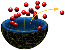
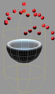
The yellow lines show the collision geometry so that you can predict where the collisions will occur. Here, the yellow lines indicate that the inside of the bowl is "cut off" from being part of the collision, so the cherries simply bounce off the bowl's top.
You can set Actual Shape as the collision geometry whether you are using the PhysX (see Actual Shape - PhysX) dynamics engine; however, the process and results are different for each.
Actual Shape provides an accurate collision but takes longer to calculate than bounding shapes or convex hulls. You may need to use the actual shape, however, for rigid body geometry that is irregular in shape or has holes, dips, or peaks that you want to consider for the collision.
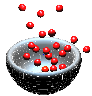
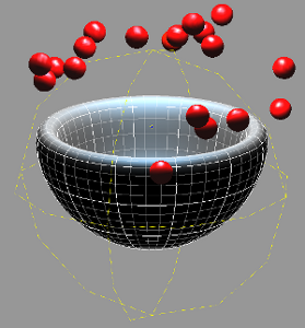
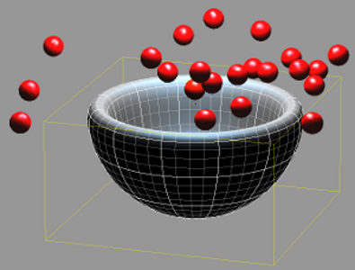
Actual Shape collision geometry is necessary for rigid body objects that have irregular shapes or have holes, dips, or peaks that you want to consider for the collision, such as this bowl with cherries falling inside of it.
If you select Actual Shape as the collision geometry for a rigid body created from an implicit object, Softimage switches to the Bounding Sphere type of collision geometry. This is because implicit objects don't have actual geometry, which Actual Shape needs to perform its calculations.
The actual shape collision geometry often requires some approximation of the rigid body's real geometry; for example, NURBS may be converted into a triangulation.
When you select Actual Shape with PhysX as the dynamics engine, collision data is created to calculate each rigid body's geometry for the collision. This collision data is based on the rigid body's actual geometry at collision time.
In the Rigid Body property editor, select Actual Shape from the Collision Type list.
Set the Detail to define how accurately you want the collision data to follow the rigid body's shape: Low, Medium, High, or Coffee break.
Set the collision geometry's resolution by changing the value for the Subdivision Level.
With actual shape collisions, collision data (also known as a penetration map, or pmap) is created for the rigid bodies. The collision data is basically a solid model (a 3D map) of the rigid body which tells the colliding objects which way to bounce based on global information about the whole rigid body.
Collision data may take a bit of time to calculate initially, but once it is done, the collisions are fast and accurate. If different rigid bodies have the same geometry (such as if they are duplicates), they can all share the same collision data. This lets you have many rigid bodies in a scene without adversely affecting the time required to calculate the simulation.
Collision data is created for each rigid body at each frame of the simulation and is kept in your computer's cache when the scene is open. When you save the scene, only the collision data for the current frame is saved (the frame at which the simulation is at the time you save). This prevents the scene file from getting too large, especially when you have many rigid bodies, each with their own collision data. When you reload the scene, the collision data is re-created for each rigid body.
Because the collision data is kept only for the frame at the time of saving the scene, this means that a rigid body with an animated deformation on it will have collision data only for one frame of its deformation state.
If you have manipulated the rigid body's center, such as by translating it from its original location, generating the collision data for the actual shape may take a long time because Softimage has to recalculate the difference in point positions at each frame of the simulation. To prevent these time-consuming calculations, you can freeze the rigid body before you run the simulation.
There are four factors which influence how well an actual shape collides with other objects:
The resolution of the rigid body's geometry (see High-resolution Geometry)
The Detail level (see Detail)
The Subdivision level (see Subdivision Level)
The number of Simulation Substeps (see Setting the Accuracy of Rigid Body Simulations)
Actual shape collisions work best on high-resolution geometry because it provides more information about the shape of the object for the calculations: the more triangles, the better. An advantage of using highly tessellated geometry is that the surface normals are smoother, which results in more realistic-looking collisions.
You can create a high-resolution geometry for the rigid body by either subdividing it in the usual way, or you can use the Subdivision Level option in this property page (see below), which won't affect the geometry outside of the simulation world.
In addition to making sure your collision geometry is detailed enough, you should try to keep the sizes of the facets roughly the same among the rigid bodies. For example, upon collision, a rigid body made of very small triangles may pass right through a rigid body made of very large triangles.
Actual shape collisions also work better on geometry that is thicker or closed — not flat, like a sheet of paper. Grids are generally not a good idea to use: it's better to use a flattened cube that has some thickness.
The Detail level lets you define how accurately you want the collision data to follow the rigid body's shape: Low, Medium, High, or Coffee break.
As you can imagine, the Low setting is the fastest and Coffee break is, well, self-explanatory. You usually need the Detail to be higher than Medium if the rigid body geometry has holes, dips, and peaks.
To illustrate which setting to use, consider a tree: the Low setting captures the large-scale shape of the tree (the trunk, large branches); Medium gets down to smaller twigs and clusters of leaves; and High considers the individual leaves. While you may need a higher setting for a tree, using Medium or High on a plain or smooth object would make no difference to the accuracy of the collision data.
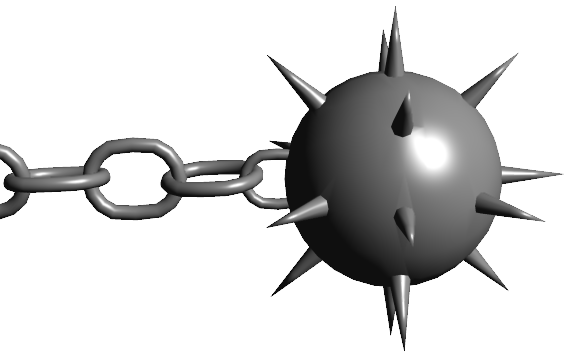
The links in this chain are fine with a Low Detail setting, but you will probably need to set the Detail to Medium or High for the spiky ball.
You can set the collision geometry's resolution by changing the value for the Subdivision Level. This option uses a simple linear subdivision rule, and won't affect the rigid body's geometry outside of the simulation world (it's independent of the rigid body's actual geometry). The higher this value, the smoother the surface used for collisions and the more accurate the collision.
For example, increasing this value for thin or low-resolution rigid bodies can help solve collision problems. This value has a profound impact on how accurate the collision is, yet it does not greatly affect the time it takes to create the collision data.
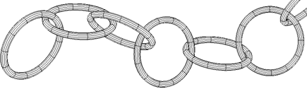
Actual Shape collision geometry can work with thin objects like these interlocking rings if the Subdivision Level is high enough.
For subdivided surfaces, the Subdivision Level defines which level of subdivision should be used for collision, independent from the one that is viewed. Only Catmull-Clark subdivision is supported.
For NURBS, this is the level of sampling of the NURBS surface used for collisions, independent from the level used in its geometry approximation property.
You may also want to use the Adaptive Substepping option, which can help make the collisions more accurate. Increasing the number of substeps per frame, as well as reducing the elasticity, can also increase the stability of actual shape collisions.
For more information, see Setting the Accuracy of Collisions for PhysX.
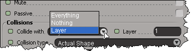
Collision layers allow you to create exclusive groups of rigid bodies that can collide with each other. Only rigid bodies with matching collision layer numbers are allowed to collide with each other. By putting rigid bodies that don't need to collide with each other in different collision layers, you can lessen the collision processing time.
For example, let's say that you have several objects that make up the body in a character that you want to have collide only with each other, but not elements in its environment. To do this, you simply assign the character's rigid bodies the same layer number (such as 1), which is different from any other rigid body in the environment (such as the default 0).
To assign a collision layer number to a rigid body:
By default, all rigid bodies are assigned a collision layer of 0, meaning that all rigid bodies can collide with each other.
The maximum number of layers that can be used is 28 (including 0).
Rigid bodies can have animated deformations applied to them. Animated deformations includes lattices, shape animation, envelopes, waves — any deform operator. If a rigid body that is part of a collision does have an animated deformation, you should select the Animatable Deformation option on the Rigid Body property page.
This option is only needed if the geometry is actually deforming over time. It is not required for animated transformations (scale, rotate, translate).
When this option is on, it correctly detects collisions using the current shape of the deform-animated rigid body at each frame. This slows down the simulation, but makes it more accurate. Unless you really need this option on (depending on the nature of the animated deformation and how accurate you need the collision to be), you should leave it off because it can use lots of memory.
When this option if off, the shape of the deformed rigid body is calculated only at the first frame of the simulation, and then this same shape is used for any collisions during the rest of the simulation.
When you create an active rigid body, it is included in all collisions by default, regardless of the collision Layer number.
You can also temporarily disable (mute) a rigid body's participation in a collision. This is useful, for example, if you have several colliding objects in a simulation and you want to quickly test the results of each one independently.
To activate the rigid body collision:
Select the rigid body you want to have collide with all other rigid bodies (in all layers).
Select the Collide with  Everything option in its Rigid Body property editor.
To mute the rigid body collision:
 Except where otherwise noted, this work is licensed under a Creative Commons Attribution-NonCommercial-ShareAlike 3.0 Unported License