Options | High Quality | Modes | Performance | Ghosting
The Display Options property controls the method used to display objects in a 3D view, in addition to other options like XRay mode, headlights, and depth cue.
There is one Display Options property for each scene camera and object view. In addition, there is one for each viewpoint and spotlight per viewport.
To display: See Choosing How Things Are Displayed in 3D Views [Basics].
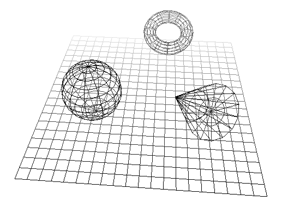
| Show Simplified Subdivision Wireframe |
Toggles visibility of a simplified version of an object's subdivision wireframe in any wireframe view in a viewport. |
| Wireframe Color |
Sets the color of the wireframe of unselected objects. Specify either the default wireframe color (set in the Scene Colors Property Editor [Preference Reference]), or the object's diffuse color. |
| XRay Mode |
Toggles the x-ray drawing style for wireframe objects (such as bones and nulls) that are inside or behind geometric objects. You can then choose an XRay Display Type. X-ray drawing is very useful when working with envelopes because you can see and select the underlying deformers while still seeing the shaded surface of the envelope. This option works in constant, shaded, and textured display modes. You can also set this option directly from the Display Mode menu. |
| XRay Display Type |
Sets the drawing style for the XRay Mode:
|
| Enable Transparency |
Toggles OGL transparency on and off in the Constant, Shaded, Textured, Textured Decal, and Realtime Shaders viewing modes. The transparency of individual objects can be controlled by either of the following: |
| Sort Transparent By |
Determines how transparent objects are sorted before they are drawn in shaded views: None: No sorting is performed. Min Depth: Objects are sorted according to the front of their bounding boxes. Max Depth: Objects are sorted according to the back of their bounding boxes. Average Depth: Objects are sorted according to the middle of their bounding boxes. Objects are always drawn from back to front, as determined by the sort order. |
| Hidden Line Surface Color |
Sets the color used to display objects in hidden line mode.
|
| Vertex Color |
Toggles the display of painted vertices in shaded view. For more information about painting colors at vertices, see Vertex Colors [Scene Elements]. |
| Blend Using Alpha in Texture Decal |
When a 3D view's display mode is set to Textured Decal, activating this option blends a material's currently displayed texture with the surface of the object to which the material is applied according to the texture's alpha channel. For more information about displaying textures in shaded viewing modes, see Managing Image Sources & Clips [Data Exchange]. |
These options control depth fading in Depth-Cue display mode, as well as the display of non-renderable OpenGL-based fog in other display modes. For example, when you set the range options, they specify the range of the Depth fading effect in Depth-Cue mode, and the density of the fog, if activated, in other display modes.
In Depth-Cue display mode, the range options control depth fading.
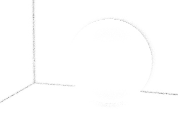
In other display modes (hidden line removal in this case), the range options control the density of the fog.
The headlight is a virtual light shining into the scene and linked to the position of the camera. It is visible in any shaded OGL display mode (Shaded, Textured, Textured Decal, and so on). When activated, it temporarily disables all other scene lights. This is useful when you want to preview the shadowed parts of scene objects. The headlight is for display purposes only, and is not renderable.
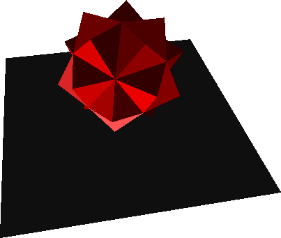
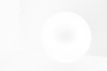
This object is lit from the bottom, creating a number of shadowed areas that are difficult to see.
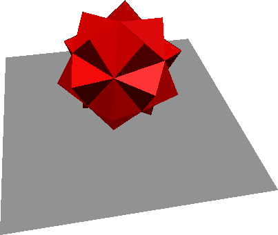
Activating the headlight lights the object from the camera's position, making the shadowed areas more visible.
Controls the options displayed in High Quality mode. Note that quality is automatically lowered during interaction, such as when orbiting the camera.
| Enable |
Enables High Quality display mode for the corresponding viewport(s). When it is disabled, viewports use a simple OpenGL display mode when High Quality is chosen. You can disable High Quality mode globally in your Display Preferences. |
| |
Deletes the cache data of shader particles from the memory. For more information on enabling the Shader Cache option, see High Quality Viewport Options. |
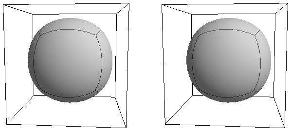
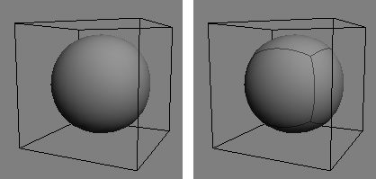
The exact settings for good screen-space ambient occlusion are very scene-dependent, but here's a rough guide for setting up in High Quality display mode:
Increase the Intensity, and if necessary decrease the Bias, until you start to see an effect.
Adjust the Radius (usually by decreasing it) until the coverage is mostly restricted to the corners and crevices, and then adjust both Radius and Scale until the extent of the coverage is about right.
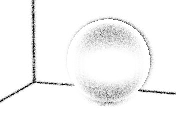
Adjust the Intensity and Bias to fine-tune the coverage and strength.
| Enable Ambient Occlusion |
Enables screen space ambient occlusion in High Quality display mode in this window. Turning this off disables ambient occlusion for all objects, whether or not they are affected by an ambient occlusion shader. |
| Enable Global Ambient Occlusion |
Calculates ambient occlusion for all objects in the scene.
|
| Radius |
The radius used for sampling. If the value is too small, there will be little effect. Like wise if the value is too big, the samples will be spread over too large an area to show much occlusion. |
| Scale |
Controls the size of the nooks and crannies that get filled by the AO effect. The smaller the scale, the larger the gaps that get filled. |
| Intensity |
The amount of dark color applied. |
| Bias |
Controls the falloff from dark to light. Near 0, there's no falloff until close to the end of the affected area while near 1, the falloff happens almost immediately. |
| |
Controls the number of iterations for the AO calculation. Higher iterations involve more computation time, but gives a smoother result, especially if the AO radius is large. |
| |
Turns on or off the blurring of the resulting AO calculation, which is eventually blended with the raw AO result. Turning it on helps to hide the “grainy” look of the raw AO result. |
| |
The number of AO samples per pixel. Higher values give better quality but take longer to draw. This value is clamped by the environment variable XSI_HIGH_QUALITY_VIEWPORT_MAX_AO_SAMPLES. |
| |
Adjusts the tolerance for the edge detection in the blurring algorithm. A lower tolerance makes the blur more sensitive to edges, but might also detect false edges. |
| |
Adjusts the blending factor between the raw AO result and the blurred result. A higher value gives more weight to the blurred result, while a lower value gives more weight to the raw AO result. |
Depth of field in High Quality display mode works by blurring pixels based on their distance from the camera. First select the Mode, then adjust the other parameters.
| Enable Depth of Field |
Enables depth of field in High Quality display mode in this window. |
| Mode |
Selects the algorithm and the options used to control depth of field: Simple or Lens. |
| Samples |
The number of DOF samples per pixel. Higher values give better quality but take longer to draw. This value is clamped by the environment variable XSI_HIGH_QUALITY_VIEWPORT_MAX_DOF_SAMPLES. |
| Mixed Viewing Mode |
Displays objects according to their individual Display properties. Turning this option on is equivalent to turning Override Object Properties off in the Display Mode menu of a viewport. Objects without individual Display properties are displayed according to the settings below. For information about setting Display properties for specific objects, see Choosing How to Display Specific Objects [Basics]. |
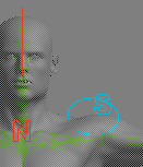
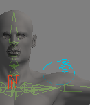
These options control how objects are displayed under different viewing conditions. The left column controls selected objects and the right column controls unselected objects.
Static controls how objects are drawn when you are not interacting in the viewports or playing back animation.
Interaction controls how objects are drawn when you are zooming, orbiting, transforming, etc., interactively in the viewports.
Playback controls how objects are displayed when playing back animation.
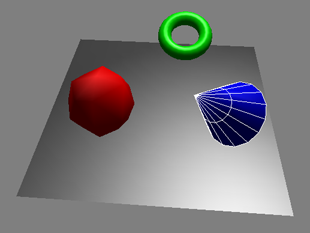
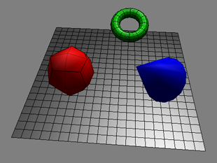
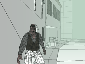
Example of using different display modes for different viewing conditions:
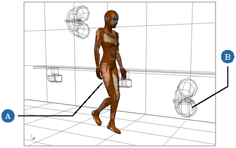
| A |
Interactive Selected: A selected static object displays in textured mode for full detail. |
| B |
Static Unselected: Unselected foreground objects display in wireframe to minimize image processing time. |
These options set the display mode for a stereoscopic camera view. The display modes let you preview the stereoscopic output without needing to render and composite the images. See Stereoscopic (3D) Camera Rigs [Cameras and Motion Blur] for information.
You can also set these options directly from the Stereo menu in any viewport or Object view in which you have a stereo camera selected in the View menu.

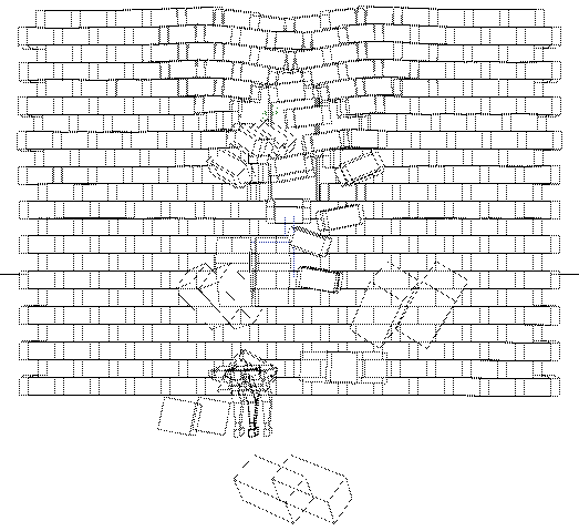
Fast playback speeds up playback of the scene in 3D views by temporarily hiding the grid and drawing simplified objects during playback. The first time you play back the scene, the frames are cached according to the cache settings. Subsequent playbacks are faster because the frames are cached.
Fast playback captures only the visible geometry, so if the camera is zoomed out when you play back a 3D cache, the geometry that was outside the view at the time of capture is not visible.
See Playing Back All Frames or Playing in Real Time [Basics].
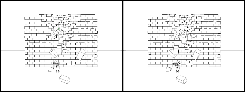
These parameters let you set up the ghosting display in the viewport for animated or simulated objects.
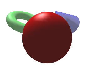
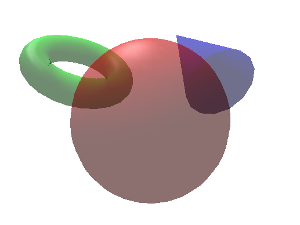
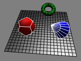
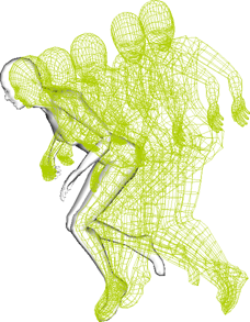
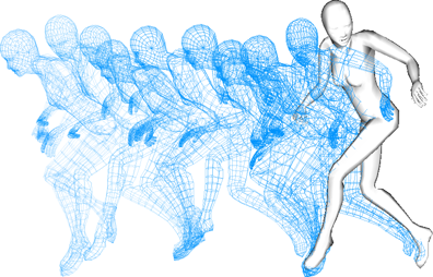
Mixer ghosting lets you see the contribution of each clip that is being blended (overlapping clips) in the animation mixer. For more information, see Ghosting Clips [Nonlinear Animation in the Animation Mixer].
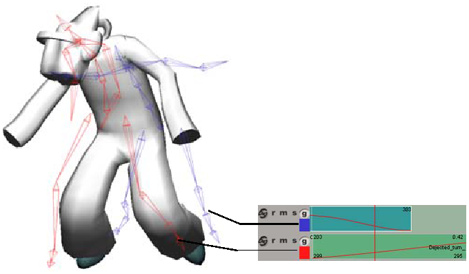
Contribution from Clip A in blue and from Clip B in red. The results of the two being blended together at the current frame is shown on the model.
Animation ghosting, also known as onion-skinning, lets you display a series of snapshots of animated objects at frames or keyframes behind and/or ahead of the current frame. Objects can be animated in any way, from keys to clips in the mixer to animated deformations and simulations.
For more information about ghosting, see Ghosting Animated Objects [Animation].
| Enable Animation Ghosting |
Toggles the display in any 3D view of ghosted shapes of animated objects. Toggling this option is the same as toggling the Animation Ghosting option in the Display Mode menu in the viewport. |
| Enable Skeleton FK/IK Ghosting |
Toggles the display in any 3D view of ghosted shapes of skeleton chains animated with inverse kinematics (position of the effector) or forward kinematics (rotation of the bone). You must select Enable Animation Ghosting for skeleton ghosting to appear. Toggling this option is the same as toggling the Skeleton FK/IK Ghosting option in the Display Mode menu in the viewport. For more information, see Blending Between FK and IK Animation [Character Animation]. |
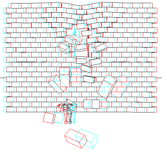
| Draw Ghosts on Top |
Ghosts are drawn on top of other objects in the viewport. |
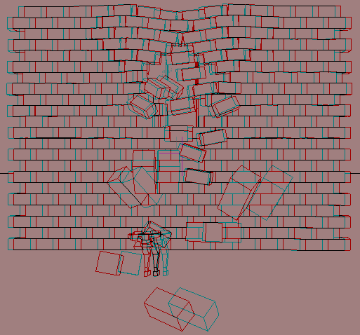
| Fade |
Ghosts become more transparent (fade out) as they get farther from the current frame. Ghosts on Static Frames (see below) cannot be faded. |
| Trail Subdivisions |
This option is active only when Trail is selected as the Ghost Type in the object's Visibility Property Editor. The trail is drawn between the first and last ghost frames using the number of ghost frames and this parameter's value to sample the motion at regular intervals. A smooth curve is then drawn through the sample points. Higher settings make the trail more closely match the underlying motion, but will take longer to compute. |
| Velocity Scale Factor |
Value that controls the length of the vector drawn when you select Velocity as the ghost display type in the object's Visibility property editor. The default value of 1 draws the velocity vector full size (Softimage units per second). |
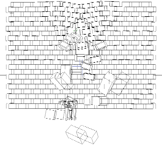
Displays ghosts only on an object's keyframes. These options work only with keys set on an object's local or global transformation parameters.
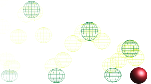
Ghosts with Keys Before set to 6 and a Key Step of 1. Ghosts in a lighter color are also displayed on frames between the dark green keys.
Lets you specify exactly which frames on which you want to display ghosts. These ghosts are not updated (they are static) as the animation changes.
 Except where otherwise noted, this work is licensed under a Creative Commons Attribution-NonCommercial-ShareAlike 3.0 Unported License