When 3D just isn't 3D enough, you need stereoscopy! Stereoscopy involves rendering one image from the left stereoscopic camera and one image from the right. The images are then superimposed on each other, but with a slight offset. After the images are composited together, the objects appear to come out of the screen when viewed with the appropriate 3D glasses.
You can create stereoscopic camera rigs in Softimage so that you can set up and render out scenes that give the illusion of this three-dimensional depth of field. When rendering a stereoscopic scene, Softimage takes into account all of the stereoscopic camera properties, and performs calculations to produce an anaglyph or parallel image that can be composited in any compositor.
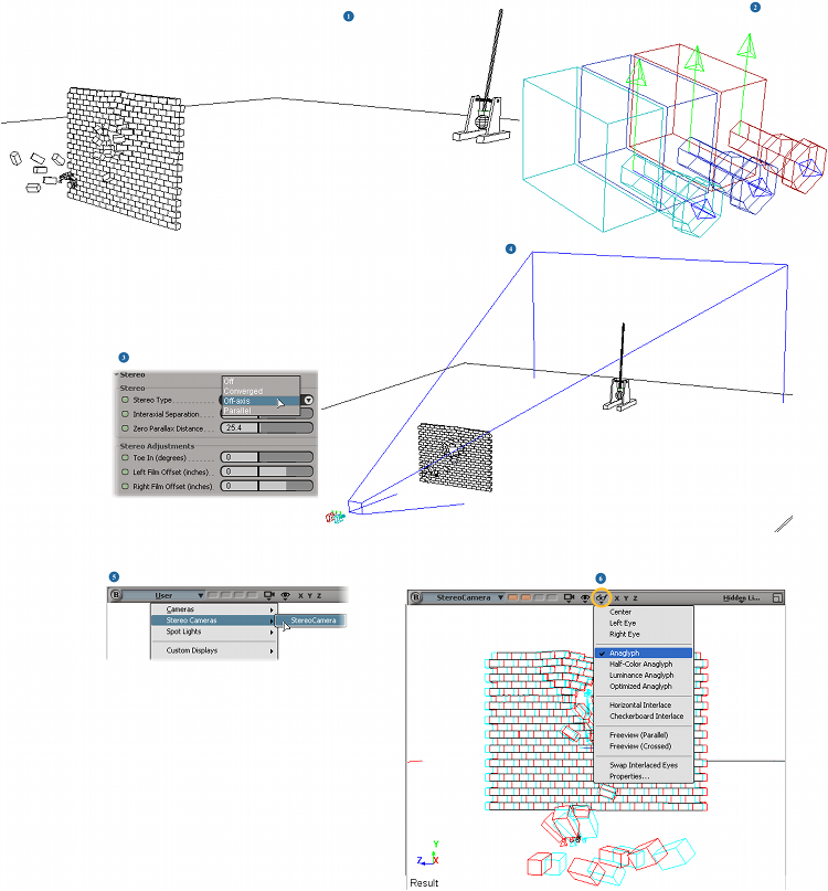
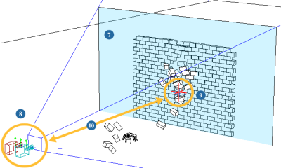
Here's a brief overview of the basic steps you need to do to work with stereoscopic cameras.
See the table following these images for links to more information about each step.
| 1 |
Set up the objects in your scene. |
| 2 |
Create a 3-camera stereoscopic rig — see Creating a Stereoscopic Camera Rig. |
| 3 |
Set the stereo camera properties in the Stereo Property Editor (Camera). Keep this property editor open to make adjustments. The Stereo Type (Off-axis, Converged, or Parallel) determines the stereo image output, so you should select it first. |
| 4 |
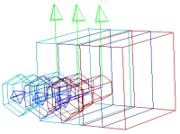
Set up the center stereo camera's typical camera properties, such as Field of View, Near/Far Clipping Planes, Projection Plane, etc. — see Camera Property Editor. Click the eye icon in a viewport and select Cones from the menu to see the selected stereo camera's frustum. |
| 5 |
Select the stereo camera you've created from the Views menu in the viewport to see from its point of view — see Viewing from a Stereoscopic Camera. |
| 6 |
Select the stereo display mode (such as Anaglyph, Horizontal Interlace, Parallel, etc.) to preview the output for the stereo camera — see Performance [Camera Display Property Editor]. |
| 7 |
Display the zero parallax plane in the viewports — see Displaying the Zero Parallax Planes. |
| 8 |
Position the stereo camera rig at the distance you want from the objects. |
| 9 |
Position the stereo camera's interest (make sure to unhide it first) at the distance you want. You may want to keep the interest on the same plane as the stereo camera rig. |
| 10 |
Use the stereo camera interest's distance from the camera to help you set the zero parallax plane's distance from the camera — see Setting the Zero Parallax Plane. |
| 11 |
Render the images from the left and right cameras, then composite them together — see Rendering and Compositing the Stereoscopic Output. |
There are two ways in which you can create a stereoscopic camera rig:
By choosing a command and having it created for you (see below).
By converting an existing camera rig into a stereo camera rig — see Making a Camera Rig into a Stereoscopic Camera Rig.
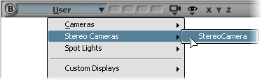
Choose Get  Primitive Camera Stereo from any menu bar to create a 3-camera stereo rig.
The stereo camera rig is created, as described below in About the Stereo Camera Rig, and its three-camera icon is displayed.
Set the options in the Stereo Property Editor (Camera) that appears.
The Stereo Type (Off-axis, Converged, or Parallel) determines how the stereo output, so you should select it first.
The stereo rig consists of the center camera (StereoCamera), and the left and right cameras (StereoCamera_Left and StereoCamera_Right):
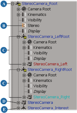
The three cameras in the rig have user keywords to easily identify them, as shown in the table in Making a Camera Rig into a Stereoscopic Camera Rig.
A stereo camera operator is applied to the left and right cameras. It sets the projection plane and copies camera parameters from the center stereo camera to the left and right cameras. The stereo camera operator is a JScript file that is located in the Addons\StereoCamera\Application\Plugins folder in the Softimage installation path.
The ICETree operator under the StereoCamera_Root node contains the StereoCameraRig compound which sets the transforms for the left and right cameras. It gets the global kinematics and stereo properties from the center camera (StereoCamera) and then sets the left and right camera's global transformation values based on these values.
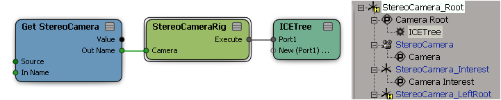
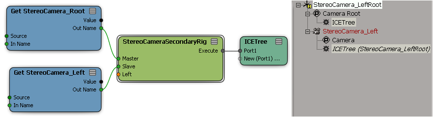
There are also ICETree operators under the StereoCamera_LeftRoot and StereoCamera_RightRoot nodes, each one containing the StereoCameraSecondaryRig compound. This compound simply copies the transforms from the StereoCamera_Root to the left and right cameras.
The transform data is computed once for one ICE tree, and is then copied by the other ICE tree. This improves performance because it ensures that the left and right camera transforms are only evaluated once.
In addition to easily creating a stereo camera rig with one command, you can also make an existing camera rig into a stereo camera rig if it meets these requirements:
The rig must contain three cameras: left, right, and center that are under a stereo camera root.
You can optionally create a custom parameter set (similar to the Stereo property set) and put it under the stereo camera root — see Custom Parameter Sets [Customizing Softimage]. The set can hold any parameters that are used to customize or control the rig.
The main components of the rig use these user keywords. The user keywords identify the rig as a stereo camera rig, which enables the display modes available only for stereo cameras — see Viewing from a Stereoscopic Camera.
Right-click on a camera node in the explorer and select User Keywords.
Enter the keywords that are required for that node, separated by commas.
You can display the user keywords in viewport by clicking the eye icon and activating the User Keywords option.
For more information on user keywords, see User Keywords.
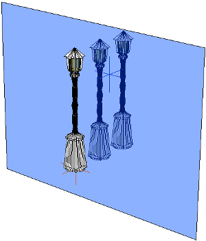
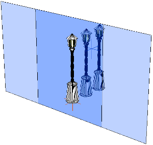
Parallax is the difference in the apparent position of an object viewed along two different lines of sight. Zero parallax is when the two views of an object are exactly superimposed on top of one another. The zero parallax plane represents the plane at which the eyes converge to see the objects, which is the screen.
Using the Zero Parallax Distance in the Stereo Property Editor (Camera), you can set the distance from the camera to where the zero parallax plane occurs for the Converged and Off-axis type stereo camera rigs.
To make an object appear to come "off the screen" (the stereoscopic effect), position the zero parallax plane closer to the camera and behind the object (so the object has negative parallax). You can see more depth if you do this. However, if the objects have too much negative parallax (too far into the audience space), it makes it difficult for the eyes to focus.
To make an object appear on the screen or recede into the background, position the zero parallax plane farther from the camera and in front of the object (so the object has positive parallax). The stereoscopic effect becomes less pronounced in this case.
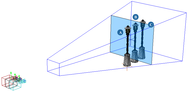
Lamp post (A) will appear to come "off" the screen (negative parallax space); lamp post (B) is on the screen (close to the zero parallax plane); and lamp post (C) recedes into the background (positive parallax space).
Make sure that objects with negative parallax are completely visible within the left and right cameras' frustums. If an object is cut off, it ruins the effect of stereoscopic images.
A rule of thumb for positioning objects is that no object should be closer to the camera than half the distance to the zero parallax plane.
In general, you probably want to position the zero parallax plane close to the location of the camera interest, which is the camera's focal point.
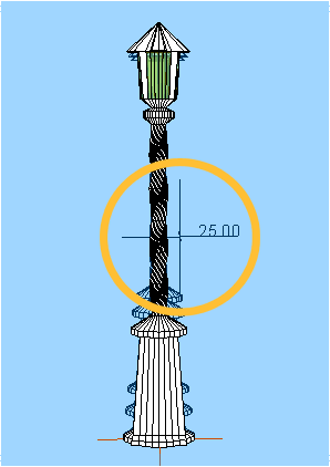
Click the eye icon in the Stereo Camera viewport and select Distance to Output Camera from the menu.
Select the stereo camera's interest to display the distance (in Softimage units) from it to the camera.
Enter this value as the Zero Parallax Distance value in the Stereo Property Editor (Camera) property editor. You can then fine-tune this as you like.
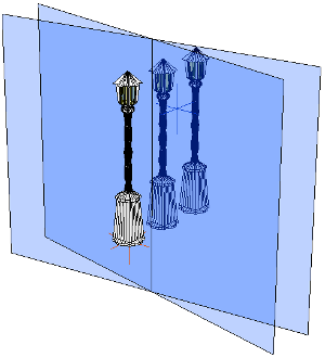
To help you visualize the zero parallax planes for the left and right cameras, you can display them in the viewports or Object view. The planes adapt to the current size of the stereo camera frustum.
If the planes for each camera aren't coplanar, an intersection line is also displayed, such as for the Converged stereo type.
By default, the planes are translucent so that you can accurately place them with the objects in your scene. However, you can change their transparency and color values as you like.
If you have selected objects isolated in the viewport, you need to also select the stereo camera to see the zero parallax plane — see Isolating Objects for more information.
You need to select the stereo camera to see the zero parallax plane in the Object view.
In the Stereo Property Editor (Camera), click the Display Toggle Zero Parallax Plane button.
This is the same as selecting the Stereo Zero Parallax Plane check boxes in the Objects property editor for all views.
In the Scene Colors Property Editor, click the Components tab and set the plane's color and transparency with the Zero Parallax Plane sliders.
To display your scene from the point of view of a stereo camera, you must select it as the Camera view in a viewport or Object view.
When you select a stereo camera, the Stereo menu appears in the view's title bar. The Stereo menu contains special display modes to let you preview the stereoscopic output in different ways.
Select the stereo camera from the Views menu in a viewport or Object view.
From the Stereo menu that appears in that viewport or the Object view, choose the display mode for the stereo camera.
For a description of each of these display modes, see Performance [Camera Display Property Editor].
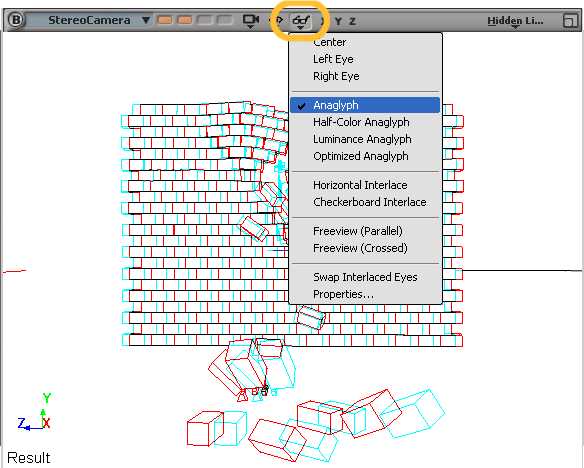
Objects in the scene are viewed with the Anaglyph stereo display mode. The left camera displays images in cyan, which are superimposed on the right camera's images that are displayed in red.
To output a scene for stereoscopy, you need to render the left and right camera images. You can do this by either:
Rendering the left and right stereo cameras in separate render passes.
Creating a group containing the left and right stereo cameras (the StereoCamera_Left and StereoCamera_Right objects only), specifying that group as the camera for the pass, and then rendering in one pass. See Rendering with Multiple Cameras for more information.
If you're rendering in one pass, set the Render Channels Output to include the [Camera] token (see Tokens and Templates). For example, the file name could be defined with this template:
[Pass]_[Framebuffer]_[Camera]
The [Camera] token returns the name of each camera being used in the render and uses it in the file name of each rendered frame so that they do not overwrite each other.
Then when you render the pass, the output would be something like this:
Stereo_Pass_Main_StereoCamera_Left.[1...500].jpg
Stereo_Pass_Main_StereoCamera_Right.[1...500].jpg
After rendering, you need to composite the left and right images together in order to create the desired stereoscopic effect, unless you're using separate projectors for the left and right cameras. When you composite, make sure that the width and height of the left and right images in the compositor match the output film format.
For compositing anaglyph images, make the image from the left camera use only the red color channel, and the image from the right camera use only the green and blue color channels. Then add these two images together and render the final output.
 Except where otherwise noted, this work is licensed under a Creative Commons Attribution-NonCommercial-ShareAlike 3.0 Unported License