You can model one half of a polygon mesh object and then symmetrize it. This creates new polygons that mirror the geometry on the original side. Unlike Duplicate by Symmetry, the new components belong to the same object and share the same clusters: no new objects or clusters are created. In addition, materials, textures, and other cluster properties are propagated symmetrically.
If you are modeling a perfectly symmetrical object, you can build half of it and then symmetrize the whole object to create the other half. If the object is not symmetrical, you can symmetrize selected polygons. For example, you can mirror just the ear of a character who has a scar on one cheek.
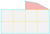
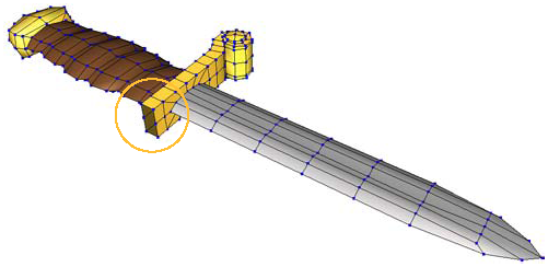
Model the polygons on one side of the object. You can use any combination of deformations (operations that move components) and topology modifications (operations that add or delete components).
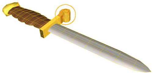
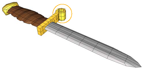
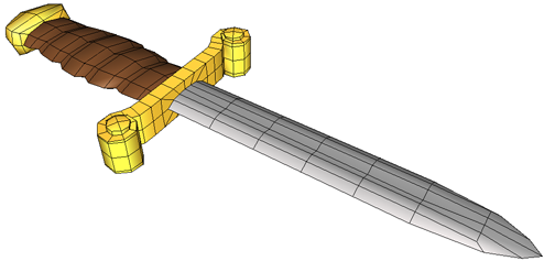
In the example below, an ornamental curlicue was added to the hilt of the dagger.
If necessary, prepare the other side of the object for symmetrization.
For example, if you intend to merge the symmetrized portions using the Weld or Bridge options, then you may need to create holes for the new polygons to fit and add vertices to aid the merge.
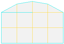
Select the polygons to be symmetrized. You can select one or more of the following:
Choose Modify  Poly. Mesh Symmetrize Polygons from the Model toolbar.
In the Symmetrize Polygon Op property editor, set the parameters as desired:
To control the plane of symmetry, see Specifying the Plane of Symmetry.
To connect the new polygons with pre-existing polygons, see Welding or Bridging Edges.
See also Notes on Symmetrizing Polygons for other information.
You can specify the plane of symmetry used for mirroring the polygons with the Reference and Plane Normal parameters on the General tab of the Symmetrize Polygon Op property editor. If Plane Normal is set to Custom Plane, then the parameters on the Custom Plane tab are also used.
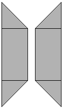
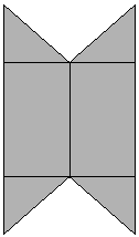
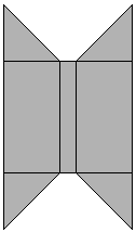
Plane Normal specifies the plane across which the polygons are mirrored:
Custom Plane allows you to specify any other plane. See the next section, Custom Planes, for more information.
When Plane Normal is set to Custom Plane on the General tab of the Symmetrize Polygon Op property editor, the parameters on the Custom Plane tab specify the plane of symmetry. You can adjust the position and orientation of the plane manually, or you can set these values automatically based on the current reference plane used for manipulation. You can also update the reference plane used for manipulation based on these values.
For more information about using reference planes for manipulation in general, see Reference Planes.
Set the values on the Custom Plane tab of the Symmetrize Polygon Op property editor:
The Position and Rotation parameters define the center of the plane of symmetry.
If Reference is set to Global on the General tab of the Symmetrize Polygon Op property editor, these values are relative to the scene origin. If Reference is set to Local, these values are relative to the object's own center.
Plane Normal specifies the plane to mirror across: X Axis (YZ plane), Y Axis (XZ plane), or Z Axis (XY plane).
If necessary, create a new reference plane. For more information, see Creating Reference Planes.
If you have already defined the reference plane you want, make sure that it is the active one. For more information, see Activating Reference Planes.
Click Update from Ref Plane on the Custom Plane tab of the Symmetrize Polygon Op property editor.
The Position, Rotation, and Plane Normal parameters are updated with the values from the active reference plane. In addition, Reference is set to Global on the General tab.
You can update the reference plane used for manipulation with the values from the Custom Plane tab of the Symmetrize Polygon Op property editor. This is useful if you want to move elements relative to the same plane you used for symmetrizing polygons.
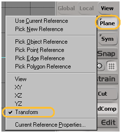
Click Set As Ref Plane on the Custom Plane tab of the Symmetrize Polygon Op property editor.
A transient reference plane is defined using the values of the Position, Rotation, and Plane Normal parameters. If Reference is set to Local on the General tab, these values are converted to global coordinates first.
In addition, the manipulation mode is automatically set to Plane and the active reference plane is set to Transform.
The Weld Options parameters on the General tab of the Symmetrize Polygon Op property editor allow you to connect the boundary edges of the mirrored polygons with the original geometry by welding (merging edges) or bridging (adding polygons between edges).
Weld connects polygons on the mirrored section and the original geometry by welding or bridging boundary edges, and activates the other Weld Options.
If Weld is on and Bridge is off, boundaries are merged (welded).
If both Weld and Bridge are on, boundaries are connected by new polygons.
If Weld is off, polygons are not connected and the other Weld Options are deactivated. Pairs of existing boundaries on the original geometry are never welded or bridged.
Bridge controls the behavior for connecting edges.
Distance controls the tolerance between facing edges. As you increase this value, more pairs of polygons become connected.
Symmetric pairs only restricts the welding or bridging operation to the new polygons created by the Symmetrize Polygon Op and their counterparts on the original geometry.
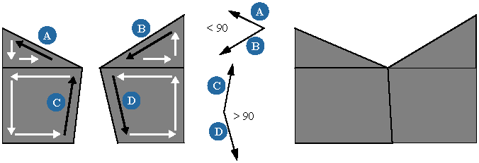
Angle > 90 connects two boundaries only if the difference between their orientations is greater than 90 degrees. This prevents the symmetry operator from connecting pairs of edges that are not facing each other. When considering the orientation of edges, remember that edges are ordered counterclockwise when normals face you.
When symmetrizing polygons, there are some things to be aware of.
When you symmetrize polygons, the new components share the same clusters as their counterparts on the original geometry. Local materials, textures, and other cluster properties (such as hard edges, polygon visibility, and the like) are extended symmetrically. In addition, weight maps and texture UV coordinates are also propagated symmetrically.
If the object is already used as an envelope when you symmetrize polygons, the envelopes weights are propagated symmetrically. However, the newly created points are assigned to the same deformers as their symmetric counterparts. In most cases, you probably want the new points to be assigned to the corresponding deformers on the other side. To fix this, you can mirror the envelope weights manually — see Mirroring Envelope Weights Symmetrically [Character Animation].
Existing shapes are extended when you symmetrize polygons. If a point on the original is included in one or more shapes, its new symmetric counterpart is added to the same shapes (new shapes are not created). For more information about shape animation in general, see Animating Shapes.
When you symmetrize polygons, the kinematic state of the object is stored. This is for performance reasons so that the operator does not need to be re-evaluated whenever you move the object. However, it also means that under certain circumstances, you will not get the expected results when you perform certain operations in the stack.
If Reference is set to Global, you should avoid performing any operation that modifies the kinematic state of the object at the point in the stack where the Symmetrize Polygon Op node is evaluated. Such operations include the following things:
Transforming the object while the Symmetrize Polygon Op node is disabled in the operator stack.
Moving the object's center while the Symmetrize Polygon Op node is disabled.
Freezing transformations while the Symmetrize Polygon Op node is disabled.
Moving the object's center or freezing transformations, and then moving the Center operator across the Symmetrize Polygon Op node in the operator stack.
When you symmetrize polygons, the effect is immediate. If you make further modifications to the object, symmetry is not maintained automatically. However, there are a few ways to maintain symmetry:
Apply a symmetry map and then manipulate components in Sym mode. For more information, see Manipulating Components Symmetrically.
Disable the operator stack from the Symmetrize Polygon Op node up before performing other modeling operations, and then re-enable it when you are done. For more information, see Disabling the Top of the Stack.
Perform other modeling operations, and then move the Symmetrize Polygon Op node above the other operators in the stack. This works best if you move the Symmetrize Polygon Op node across only deformation nodes. In certain cases, moving the node may not be allowed or may give unexpected results. For more information, see Changing the Order of Operators.
 Except where otherwise noted, this work is licensed under a Creative Commons Attribution-NonCommercial-ShareAlike 3.0 Unported License