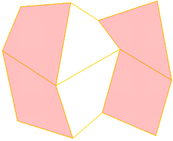
Dicing subdivides polygons by adding edges at regular intervals along one or more perpendicular planes.
The cutting planes used for dicing are specified by a combination of the Style, Frame, and Merge parameters in the Dice Polygons Op property editor.
Style selects the axes to cut along. The result is a crisscross pattern across the Z = 0 plane (XY), X = 0 plane (YZ), Y = 0 plane (XZ), or all planes (XYZ).
Frame determines which set of axes to use:
Local Component uses the local reference frame of the affected polygons. The local reference frame can be based on each individual polygon, each group of adjacent polygons, or all selected polygons, depending the Merge parameter. Local Component has no effect if you diced an object instead of components.
Merge determines how the components are diced:
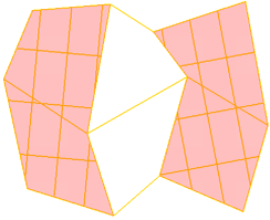
Adjacent Polygons performs one dice operation on each group of connected polygons.
All performs a single dice operation on all polygons together, whether or not they are connected.
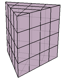
You can specify the number of slices directly using the X, Y, and Z sliders, or specify a uniform grid:
To set the number of slices directly, set Number of Slices X, Y, and Z to the desired number in each direction. The slices are spaced so that they evenly divide the bounding box with respect to the reference set by the Frame parameter.
To use a uniform grid for slicing, activate Grid Like and set the desired Grid Size. Softimage automatically calculates the required number of slices in each direction.
Dicing sometimes creates very small edges and polygons when a slice passes close to an existing vertex. You can eliminate these small components using Point Snap Tolerance — if a new point created by the dice operator is closer to an existing point than the tolerance value, the new point gets snapped to the existing point and welded. As a result, some of the new edges are no longer exactly parallel to the cutting plane, but no existing points get moved.
To break the object apart into separate, disconnected polygons and islands of polygons along the new edges, activate Disconnect Edges. The dice operator creates pairs of boundary edges instead of simple edges. The effect is the same as if you selected all
new edges created by the dice operation and then chose Modify  Poly. Mesh Disconnect Edges.
 Except where otherwise noted, this work is licensed under a Creative Commons Attribution-NonCommercial-ShareAlike 3.0 Unported License