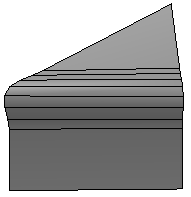
The Modify  Poly. Mesh Bevel Components command on the Model toolbar smooths corners by adding polygons. You can bevel polygons, points, and edges. In addition to
a simple flat bevel, you can use multiple subdivisions to achieve a rounded effect.
Poly. Mesh Bevel Components command on the Model toolbar smooths corners by adding polygons. You can bevel polygons, points, and edges. In addition to
a simple flat bevel, you can use multiple subdivisions to achieve a rounded effect.
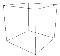
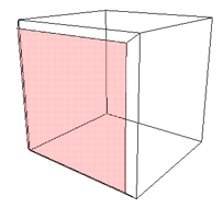
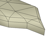
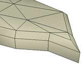
Select one or more polygons, edges, points, or clusters on a polygon mesh object.
Note that if you select polygons, only the contour of the selection is beveled. The interior edges are not beveled. This means that you cannot bevel a closed object like a cube by beveling all its polygons because the selection has no contour — instead, select all its edges.
Also note that if the object has been scaled non-uniformly along different axes, then the beveling will also be non-uniform. If you want uniform beveling, freeze the object's scaling before applying the bevel. For more information about freezing transformations, see Freezing Transformations.
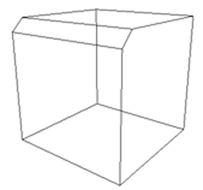
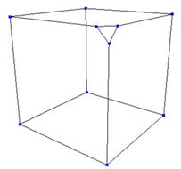
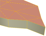
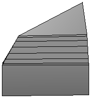
Choose Modify Poly. Mesh Bevel Component.
The components are beveled and the Bevel Op property editor opens.
Adjust the parameters as described in the sections that follow.
If you are beveling selected points, you can adjust only the Distance. None of the other parameters are available for points.
Distance, Type, and Units on the General tab of the Bevel Op property editor control the size of the bevel:
Distance is the amount of beveling. The values depend on the Type and Units settings.
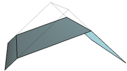
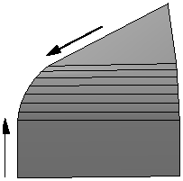
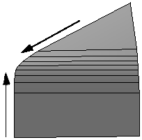
Type controls the direction in which Distance is measured:
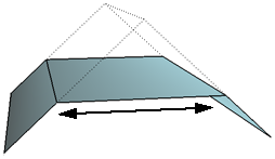
Bevel width is the width of the new polygons created by the Bevel operator.
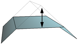
Along bisectors is the distance between the original, unbeveled edge and the new polygon created by the Bevel operator.
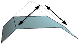
Along adjacent polygons is the distance between the original, unbeveled edges and the new edges created by the Bevel operator.
Units determines the values used by the Distance slider:
In addition, Center controls the position of the bevel, allowing you to create lopsided bevels.
Joint options on the General tab of the Bevel Op property editor control how beveling behaves at joints between edges.
As you increase the bevel distance, the beveled edges may collide with other components on the object, resulting in overlapping polygons. This problem can be especially acute near sharp corners.
When Manage collisions (available on the General tab of the Bevel Op property editor) is on, the Bevel operator automatically collapses points that collide with each other so that no overlapping occurs. Note that only collisions between adjacent components are detected.
You can turn this option off if you need to ensure that the number of vertices does not change when the bevel distance is animated, or if you prefer to manually clean up any overlapping polygons.
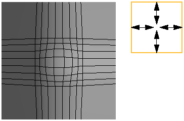
The Uniform miter option on the General tab of the Bevel Op property editor controls the tesselation at junctions between two beveled edges:
When this option is off, 2-edge junctions with three or more polygons on the same side are tesselated by polygons in order to preserve the surrounding geometry.
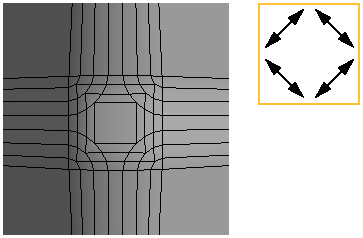
When this option is on, all 2-edge junctions are single edges. This may result in cleaner geometry in the beveled region but may also change the shape somewhat in the surrounding areas.
You can automatically mark the edges created by the Bevel operator as hard. This is useful for creating discontinuities in the shading to achieve a faceted appearance. There are three independent options for Hard edges on the General tab of the Bevel Op property editor:
On contour marks the outer edges created by the Bevel operator as hard.
On 3+ edge junctions marks the edges at junctions between three or more beveled edges as hard.
Min angle for 2 edge junction controls the minimum angle for marking 2-edge junctions as hard. If the dihedral angle between two adjacent polygons on the same side of the beveled edges is greater than this value in degrees, the junction is marked as hard. A value of 0 marks all 2-edge junctions as hard, and a value of 180 marks none as hard.
If you set this angle to the same value as the Angle for automatic discontinuity in the object's Geometry Approximation property, then discontinuities on the object propagate to the beveled region.
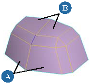
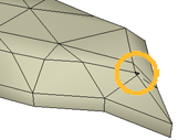
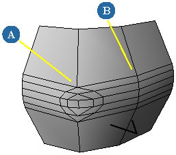
An edge on 2-edge junction marked as hard. The slider controls the minimum angle between any two polygons on the same side (either the pair marked A or the pair marked B) for the corresponding edge to be marked hard.
The options on the Rounding tab of the Bevel Op property editor allow you to create rounded bevels with multiple subdivisions.
Sharpness on the Rounding tab of the Bevel Op property editor controls the shape of the profile. A value of 1 uses an arc-like segment (the default). Higher and lower values increase or decrease the tension, or the influence of the tangency of the adjacent polygons, similar to adjusting the length of Bézier control handles. A value of zero gives a flat profile.
You can also control the shape of the profile using the Extrapolation slider as described in Extrapolating the Rounding Displacement.
The Junctions options control the tesselation where beveled edges meet. This lets you smooth the shape and shading on the insides of junctions.
Tesselate is the "master control" that turns tesselation on or off. When this option is off, no junctions are tesselated and the other Junctions options are unavailable. When this option is on, all junctions of three or more beveled edges are tesselated and you can use the other options to tesselate 2-edge junctions and control other aspects of the tesselation.
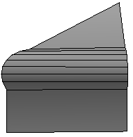
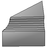
2 edge junction min angle controls the minimum angle for tesselating 2-edge junctions. If the dihedral angle between two adjacent polygons on the same side of the beveled edges is greater than this value in degrees, the junction is tesselated. A value of 0 tesselates all 2-edge junctions, and a value of 180 tesselates none.
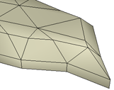
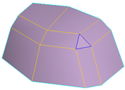
2 edge junction min angle: 2-edge junctions are tessellated where polygons meet at sharper angles (A), but not where they meet at flatter angles (B).
Extrapolation Amount on the Rounding tab of the Bevel Op property editor multiplies the displacement of the rounding effect above the flat bevel. Positive values produce exaggerated bulges, and negative values produce incised bevels. A value of zero produces no extra displacement, and a value of – 1 produces an exactly inverted displacement.
When Amount is nonzero, use Keep tangency to ensure that the borders of the beveled region remain continuous with the adjacent polygons.
 Except where otherwise noted, this work is licensed under a Creative Commons Attribution-NonCommercial-ShareAlike 3.0 Unported License