


 Use the standard 3ds Max Rotate transform to adjust a biped's posture by rotating its links. Use the main toolbar button, or right-click and choose
Rotate from the quad menu.
Use the standard 3ds Max Rotate transform to adjust a biped's posture by rotating its links. Use the main toolbar button, or right-click and choose
Rotate from the quad menu.
To make biped movement appear natural, certain biped joints are limited in how they can rotate, such as the elbows and knees. When a joint can rotate in all three axes, X, Y, and Z, it is said to have three degrees of freedom (DOF). A joint’s DOF can be modified by selecting it and then setting options on the Locks rollout of the Hierarchy panel.
The table below shows the degrees of freedom of each link. Biped allows a bit greater freedom than most human bodies are capable of. All rotations are performed in the local coordinate system.
To rotate the biped pelvis in all three dimensions, refer to Pelvis as Ball Joint.
Some biped parts have special-case conditions that govern how you can transform them, as described in the table and sections that follow.
| Biped Link | Link Name | Free Axes | Comments |
|---|---|---|---|
| Center of mass | Bip001 (default) | X, Y, Z | Rotates entire biped |
| Pelvis | Pelvis | X, Y, Z | If feet are planted, adjusts legs to keep feet and toes above ground |
| Head | Head | X, Y, Z | |
| Neck | Neck | X, Y, Z | Neck orientation does not affect head orientation |
| Spine | Spine, Spine1-4 | X, Y, Z | Spine rotation adjusts overall balance |
| Tail | Tail, Tail1-4 | X, Y, Z | |
| Clavicles | R Arm, L Arm | Y, Z | Shoulder orientation does not affect clavicle orientation |
| Shoulders (upper arm) | R UpperArm, L UpperArm | X, Y, Z | Rotating pivots from shoulder to wrist |
| Elbows (lower arm) | R Forearm, L Forearm | X, Z | Hinge plus special rotation |
| Hips (upper leg) | R Thigh, L Thigh | X, Y, Z | Rotating pivots from hip to ankle |
| Knees (lower leg) | R Calf, L Calf | X, Z | Hinge plus special rotation |
| Hands | R Hand, L Hand | X, Y, Z | |
| Feet | R Foot, L Foot | X, Y, Z | If feet are planted, adjusts legs to keep feet and toes above ground |
| Fingers | Finger0, 01, 02 Finger1, 11, 12, amd so on | X, Y, Z | Finger bases have three free axes; other finger joints have Z only |
| Toes | Toe0, 01, 02 Toe1, 11, 12, and so on | X, Y, Z | Toe bases have three free axes; other toe joints have Z only |
The pelvis can be rotated in all three axes: X, Y, and Z. This ball joint provides three degrees of freedom, improving the flexibility of animating with a biped, because the pelvis gyrations are isolated from the center of mass (COM) rotation. This causes the COM to assume a smoother trajectory, which also influences the biped’s head and arms. As a result, they will look more natural moving in the body’s COM rotational space.
It's important to be aware of the following behavioral changes resulting from this:
Special Rotation: Elbows and Knees
Elbows and Knees perform a special rotation when you rotate them about their X axis. They don't actually rotate around their X axis; this does not make sense because they have one degree of freedom. Instead, the upper and lower arm/leg are rotated together about an invisible axis defined by the line stretching from the shoulder to the wrist, and the hip to the ankle. This special rotation can be very useful for positioning the arms and legs.
The special rotation can also be useful for creating characters with reverse knee bends. When the knees are rotated backward, at more than a 90-degree rotation from the front-facing human knee posture, Biped assumes the character has backward knees or bird legs, and uses this as a reference position for all .bip motions.
Rotating the forearm along the X axis rotates the arm elements about an invisible axis between the shoulder and wrist.
Biped uses only the spine, in conjunction with the center of mass, to maintain the biped's balance. Because of this, rotating all of the spine or any one of its links causes the horizontal position of the body to change relative to its center of mass. These adjustments are performed in the center of mass's local reference coordinate system, ensuring that the figure will rotate naturally about its center of mass; for example, during flips in the air.
On the Motion panel Key Info rollout, you can turn this behavior off by setting Balance Factor to 0.0 for corresponding horizontal center of mass keys. The Balance Factor control is in the Body group on the rollout.
Independent Orientation: Arms, Head, Feet
Changing the orientation of a clavicle (the root Arm object) changes the position, but not the orientation, of its corresponding upper arm. In effect, the clavicles are a support from which the arms are suspended.
Likewise, the orientation of the neck changes the position, but not the orientation, of the head. Although linked to the neck, the head typically rotates independently of the neck, and interpolation of these individually set orientations produces more natural-looking motion.
Similar to the head and arms, changing the orientation of the upper or lower leg changes the position, but not the orientation, of the corresponding foot. In this way, the foot orientation remains relative to the ground plane.
Adjusting Keys with TCB Rotation
Rather than creating extra keys to fine-tune the motion of the biped limbs, you can use the TCB controls to adjust ease in, ease out, and limb trajectory on keys that already exist.
Visualizing Rotation Animations with Function Curves
Another way to visualize your rotation animation is through the Curve Editor. Each key you add is displayed and connected to other keys, creating a curve that represents your animation. You can use either the TCB Rotation Controller or the Euler XYZ Controller (on the Quaternion/Euler rollout) to display your rotation curve as Quaternion or Euler, respectively. Each controller affects the curve differently based on separate rotation calculations. To learn more about this, refer to Working with Euler Curves on Biped Animation.
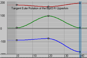
Tangent Euler Rotation curve
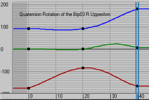
Quaternion Rotation curve
To change TCB for a biped arm:
 (Trajectories).
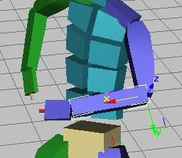
 Select a biped arm.
 (Next Key) or
  (Previous Key) to locate an arm key.
The trajectory changes to reflect the new parameters. Play the animation to see the change.