


 Command entry:
 Application menu
  Import Select File To Import dialog Files Of Type drop-down list Choose AutoCAD Drawing (*.DWG, *.DXF). Choose a DWG or DXF file. Click Open. AutoCAD DWG/DXF Import Options dialog
In most cases, when using the same data with two or more different Autodesk products, it's preferable to use the File Link Manager to connect to drawing files: This lets you maintain a “live” link between the applications. However, if you prefer to do so, you can also use the Import command to bind to the drawing file immediately.
When you import a drawing file, 3ds Max converts a subset of the AutoCAD, AutoCAD Architecture (formerly Architectural Desktop), or Revit objects to corresponding 3ds Max objects.
After you select a drawing file to import, the AutoCAD DWG/DXF Import Options dialog is displayed. After choosing options and proceeding with the import, you are presented with editable meshes, editable splines, and PRS controllers. Each nested block maintain its parent-child hierarchy and is imported as “Block/Style Parent”. In addition, if a single drawing object creates both mesh and spline geometry, you will find objects referred to as “Linked Geometry” in the scene. Block/Style Parent and Linked Geometry objects appear in the modifier stack on the Modify panel.
If you are using AutoSurf or AutoCAD Designer, use the AutoCAD command 3DSOUT to export mechanical models to 3ds Max. You can also explode the mechanical models and then import the resulting file, but some data will not appear in the AutoCAD drawing file.
The current DWG import utility contains many improvements, including enhanced DWG compatibility and greater user control and customizability; however, some features were lost from the DWG Importer found in versions of 3ds Max prior to 3ds Max 7. For this reason, 3ds Max retains the legacy DWG Import functionality.
Features Unique to the current DWG Import System
Support of Multiple Materials on Imported ACIS Solids
3ds Max supports multiple materials per object in DWG files exported as ACIS solids from Revit Architecture/Structure/MEP 2008 and later, as well as solid primitives created in AutoCAD Architecture 2008 (formerly ADT) and later. Imported solids can have Multi/Sub-Object materials that you can view and manipulate in the Material Editor.
Legacy AutoCAD DWG import does not support multiple materials on ACIS solids.
When 3ds Max imports a DWG file from AutoCAD or Revit Architecture (version 2008 and later) with either the Layer, Blocks as Node Hierarchy, Split by Material” or the Entity, Blocks as Node Hierarchy derivation methods, multiple material IDs are readable and editable as Multi/Sub-Object materials in the Material Editor.
3ds Max reads each face of an imported AutoCAD/Revit solid to determine if it contains any material IDs that can be imported. If 3ds Max reads more than one material ID from a solid, it translates each material ID on import and re-assigns it to the object.
3ds Max creates Multi/Sub-Object materials only if it finds more than one material ID; if an ACIS solid contains only one material ID, 3ds Max creates and assigns a standard/architectural material instead.
Multi/Sub-Object Material Naming
Versions prior to 3ds Max 7 read the material ID information from the color ID of the AutoCAD/Revit material ID’s face. The current importer creates a Multi/Sub object material for every translated per face material ID each time you import a DWG file that contains an AutoCAD/Revit solid.
When 3ds Max finds multiple materials assigned to an ACIS solid and creates a Multi/Sub-Object material, the Multi/Sub-Object material consists of instances of standard architectural scene materials.
Material IDs are unique within one DWG file. However, the same material ID might appear in two different files, such as Basic Wall: Generic – 12” Masonry. If a naming conflict arises when two scenes are merged, 3ds Max applies the last loaded material used in the Multi/Sub object material.
For example, if you import two files, file1.dwg and file2.dwg, and they both contain a material named Brick; the Brick material used is the one from the second file (file2.dwg).
Or, if file1.dwg contains a material named Brick that is internally stored as material ID 222 and file2.dwg contains a different material stored as ID 222, the material used in the scene when they are imported is file2.dwg’s material.
If two solids share the same material ID, they will share the same Multi/Sub-Object material.
DWG ACIS solids import as solid objects in 3ds Max. You cannot separate faces of an ACIS solid object unless you apply the Edit Poly or Edit Mesh modifier.
ACIS solid materials display in the Material Editor, along with any other imported materials.
When you apply a bitmap material to an ACIS solid, it is applied to every side of the object. For example, a brick bitmap material that you apply to a wall object appears on both sides and all edges of the wall. If you want to apply a material to each face ID, you can use a Multi/Sub Object material so you can assign sub-materials to each face ID.
When you import ACIS solids into 3ds Max, procedural textures are not imported, only materials For example, a brick wall in Revit may have mortar lines procedurally drawn on it in red, but if the object is an ACIS solid, the mortar lines, which are procedural hatches, are lost in 3ds Max
When an ACIS object’s materials are shown as a Multi/Sub-Object material in the Material Editor, each material name appears in the Material/Map Browser, for example, Default wall or Basic Wall: Generic – 12” Masonry.
Polymesh DWGs import as polymesh geometry in 3ds Max. Unlike ACIS solids, you can modify and edit any face of a polymesh object.
Polymesh Objects and Materials
When you import a polymesh DWG file, 3ds Max considers each polymesh face as a separate entity, with one material permitted per entity, which allows it to contain multiple materials.
You can apply a bitmap material to the different faces of polymesh geometry, unlike ACIS solids, where you would need to use a Multi/Sub-Object material to create the same effect. For example, you can select the outside face of wall and apply a brick bitmap material and also apply a diffuse material on the inside wall to simulate white paint.
When you import a polymesh DWG file, every material used in the scene appears in the Material Editor as a separate material, where you can edit it.
When the Material Editor shows a polymesh object’s materials, each material name appears in the Material/Map Browser, for example, Default wall or Basic Wall: Generic – 12” Masonry.

 Application menu Import.
The Import Options dialog contains three panels, documented in the following topics:
DWG/DXF Import: Geometry Panel
DWG/DXF Import: Spline Rendering Panel
A Note on Large-Scale Drawings
If you attempt to import geometry that is created very far from the origin or contains a very large bounding box in tools like AutoCAD, the 3ds Max viewports and transform tools do not respond properly. When you use them, the cursor does not move smoothly.
For example, if you have a file that is a mile wide, but your system units are millimeters, you have a scene width of 1.6 million units, which is too great a value. If you change your system unit to feet, this is less taxing on the system.
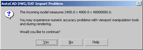
If any side of the scene's bounding box measures larger than ± 1,000,000 system units, you will see the following dialog:
The Geometry panel of the Import Options dialog controls how 3ds Max derives AutoCAD primitives and whether 3ds Max uses the scene material definitions when linking to or reloading the AutoCAD drawing. It also presents options for geometry translation and for toggling inclusion of certain elements in the DWG or DXF file.
The Layers panel of the Import Options dialog lets you choose specific layers for importing from the DWG or DXF file.
The Spline Rendering panel of the Import Options dialog lets you determine how spline objects imported from DWG and DXF files are displayed in the viewports and how they're treated by the 3ds Max renderer.