 Command entry:
 Application menu
  Import Select File To Import dialog Files Of Type drop-down list Choose Legacy AutoCAD (*.DWG). Choose a DWG file. Click Open. Import AutoCAD DWG File dialog
The AutoCAD DWG/DXF Import Options dialog introduced prior to 3ds Max 7 contained many improvements, including enhanced DWG compatibility and greater user control and customizability; however, some things were also lost from the DWG Import found in previous versions of 3ds Max. For this reason, 3ds Max retains the legacy DWG Import functionality.
Features Unique to the Legacy DWG Import System
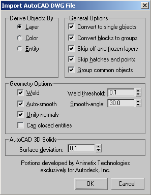
Names each 3ds Max object based on the object layers specified in the drawing file. The layer name is followed by a number for each object from that layer. For example, an object on the layer BASE becomes BASE.01. If Convert To Single Objects is turned on, objects on the same layer become a single 3ds Max object.
Derives the name of each 3ds Max object based on the object's layer color in the drawing. The AutoCAD color number is followed by a number for each object using that layer color. For example, objects on a layer that is set to the color red (Color number 001) become COLOR001.01. Colors assigned by object are ignored in favor of colors assigned by layer. If Convert To Single Objects is turned on, objects assigned the same layer color become a single 3ds Max object.
Combines multiple objects in the drawing file into a single 3ds Max object. Objects are combined according to the current Derive Objects By setting and their 3ds Max object type. Explicit mesh objects are combined. Shapes with no Z axis extrusion are combined, as are shapes with the same Z axis extrusion amount. Shapes with differing amounts of Z axis extrusion are assigned an Extrude modifier and are not combined.
Places all objects in a block entity into a 3ds Max group that uses the name of the block entity and the number .01. For example, a block entity named CHAIR becomes a collection of 3ds Max objects inside a group named [CHAIR.01].
Multiple insertions of the block entity are converted to instances of the 3ds Max group. For example, a second insertion of the block, CHAIR, becomes an instance of [CHAIR.01] named [CHAIR.02].
When Convert Blocks To Groups is turned off, block definitions are ignored and block insertions are treated as separate objects, similar to exploding blocks in AutoCAD.
Sets whether coincident vertices of converted objects are welded according to the Weld Threshold setting. Welding smoothes across seams and unifies normals of objects with coincident vertices. To use the Weld option, first turn on Convert To Single Objects, because welding occurs only for vertices that are part of the same object.
Analyzes the face normals of each object and flips normals where necessary, so they all point out from the center of an object. If the imported geometry is not properly welded, or if 3ds Max can't determine the object's center, normals might be oriented in the wrong direction. Use the Edit Mesh or Normal modifiers to flip normals.
When Unify Normals is turned off, normals are calculated according to the face vertex order in the drawing file. Face normals for 3D Solids are already unified. Turn off Unify Normals when importing 3D Solid models.
Applies an Extrude modifier to all closed entities, and turns on the Cap Start and Cap End options of the modifier. The Extrude modifier Amount value for a closed entity with no thickness is set to 0. Capping makes closed entities with thickness appear solid and closed entities without thickness appear flat. When Cap Closed Entities is turned off, the Extrude modifier Cap Start and Cap End options for closed entities with thickness are turned off. No modifiers are applied to closed entities without thickness, except for Circle, Trace, and Solid.


