 Command entry:
 Application menu
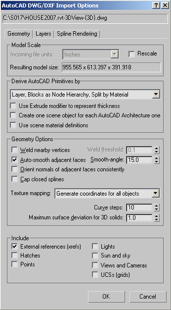
  Import Select File To Import dialog Files Of Type drop-down list Choose AutoCAD Drawing (*.DWG, *.DXF). Choose a DWG or DXF file. Click Open. AutoCAD DWG/DXF Import Options dialog Geometry panel
The Geometry panel of the Import Options dialog controls how 3ds Max derives AutoCAD primitives and whether 3ds Max uses the scene material definitions when linking to or reloading the AutoCAD drawing. It also presents options for geometry translation and for toggling inclusion of certain elements in the DWG or DXF file.
Allows rescaling the incoming geometry by a factor corresponding to the most common unit type used. The importer tries to detect the units of the DWG file being imported, compares those units with the 3ds Max system units, and then provides the appropriate conversion factor.
For example, if a drawing file is built in millimeters and 3ds Max has its System Units set to inches, the AutoCAD DWG/DXF Import Options dialog automatically has Rescale on and the Incoming File Units set to millimeters.
When there is a scale disparity, It's generally advisable to rescale an incoming drawing to more realistic units to account for the precision limitations of 3ds Max compared to AutoCAD. For instance, if you import an airport designed in millimeters in AutoCAD, set Incoming File Units to Feet or Meters. For further information, see A Note on Large-Scale Drawings.
Derive AutoCAD Primitives By group
This group box contains options for translating the geometry in the DWG or DXF file to 3ds Max format.
Choose the method for deriving imported AutoCAD primitives from this drop-down list. The options are as follows:
Each block is imported separately as a hierarchy, with the block itself as the parent object and its constituent parts as child objects. The child objects of the block are combined by layer.
For example, take an AutoCAD file with six objects in layer A: three have a Brick material and three have a Stone material. Using this option, this file would be imported in the form of two objects, or nodes, one containing the Brick material and the other with the Stone material.
Each block is imported separately as a hierarchy, with the block itself as the parent object and its constituent parts as child objects. The child objects of the block are combined by layer.
On import, ACIS solids and polymesh geometry can support multiple materials. For polymesh geometry, one material is supported per face. For an ACIS solid, if the solid has more than one material associated with it, a multi/sub object material is created that contains the materials used. If the solid has only one material associated with it, a standard/architectural material is assigned instead.
One benefit of this option is that you can apply instanced animation controllers to block subcomponents and thus, by transforming a single member, transform all members at once. For example, in a scene containing a conference table with six chairs around it, you could move all of the chairs simultaneously by moving a single chair.
Another advantage is that all geometry is instanced, so edited UVs and normals and other modifications need be done only once.
Multiple materials per object are supported with this option, if needed. If the object is an ACIS solid, and has more than one material associated with it, a multi/sub object material is created containing the materials that can be edited in the Materials Editor. If the solid has only one material associated with it, a standard/architectural material is assigned instead. If the object is a Polymesh, one material per face is supported.
When on, objects with thickness receive an Extrude modifier to represent the thickness value. You can then access the parameters of this modifier and change the height segments, capping options, and height value. Unavailable with the Layer, Blocks As Node Hierarchy option.
When off, objects with thickness (and closed capped objects) are converted directly to mesh objects.
AutoCAD Architecture (formerly Architectural Desktop or ADT) objects are imported as a single object instead of being separated into their constituent components. This means that if you import an ADT door object, the door is represented as one object instead of three (frame, step, door). Turning on this switch makes importing faster and the scene size smaller.
When on, 3ds Max checks the current scene for any currently used materials with the exact same name as a material name in the incoming DWG file. If a match is found, the importer does not translate the drawing's material, but instead uses the material defined in the scene.
When off, the File Link Manager always uses the material definitions contained in the DWG file, and will overwrite scene materials with the same name, regardless of which objects the material is applied to. All material definitions stored in the DWG file are reloaded (even when using a selective reload). If you make changes to a linked material, in Autodesk VIZ, then reload, those changes will be lost (if the switch is off).
Assigns smoothing groups according to the Smooth Angle value. Smoothing groups determine whether faces on an object render as a smooth surface or display a seam at their edges, creating a faceted appearance.
Analyzes the face normals of each object and flips normals to make their directions consistent. If the imported geometry is not properly welded, or if 3ds Max can’t determine the object's center, normals might be oriented in the wrong direction. Use the Edit Mesh or Normal modifiers to flip normals.
When this option is off, 3ds Max calculates normals according to the face vertex order in the drawing file. Face normals for solid objects are already unified. Make sure this option is off when importing drawings containing solid objects.
You should also make sure this option is off when working with AutoCAD Architecture files.
AutoCAD solids will never have their normals unified, regardless of the setting of this import toggle. Solids generate faces and normals correctly.
Applies an Extrude modifier to all closed objects, and turns on the Cap Start and Cap End options of the modifier. The Extrude modifier Amount value for a closed entity with no thickness is set to 0. Capping makes closed entities with thickness appear solid and closed entities without thickness appear flat. When Cap Closed Objects is turned off, the Extrude modifier Cap Start and Cap End options for closed entities with thickness are turned off. No modifiers are applied to closed entities without thickness, except for Circle, Trace, and Solid.
The texture mapping settings affect the loading time of models that have many objects with stored UVW Coordinates for texture mapped materials.
When drawings are imported, objects are added to the scene as Editable Mesh objects that do not have UVW coordinate assignments. Before assigning materials to imported objects, you'll need to apply a UVW Map modifier to add texture coordinates. When you then apply the material and the material or texture map is set to Show Map in Viewport, the texture map is displayed if the viewport is set to Smooth + Highlights. If the UVW Map modifier is not applied, the object turns gray and you'll see a Missing Map Coordinates dialog when you render the scene.
This option gives you faster loading speed, but no UVW coordinate generation.
This option tells the DWG/DXF Importer to create UVW coordinates, but loading time is increased while the coordinate generation occurs.
Specifies the maximum allowable distance from the 3ds Max surface mesh to the parametric 3D solid surface. Small numbers produce more accurate surfaces with a greater number of faces. Large numbers produce less accurate surfaces with fewer faces. In most cases, the default value suffices. Default=1.0.
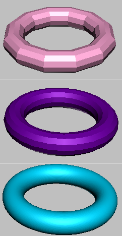
Imported 3D solid with different Surface Deviation settings
Top: Surface Deviation=10.0
Center: Surface Deviation=1.0 (the default)
Bottom: Surface Deviation=0.1
This group allows you to toggle the inclusion of specific parts of a drawing file during the import process.
Imports Sun and Shadows position from the drawing file (AutoCAD / AutoCAD Architecture 2008 and Revit 2008 only).


