Vertices are points in space: They define the structure of other sub-objects (edges and polygons) that make up the poly object. When you move or edit vertices, the connected geometry is affected as well. Vertices can also exist independently; such isolated vertices can be used to construct other geometry but are otherwise invisible when rendering.
At the editable poly Vertex sub-object level, you can select single and multiple vertices and move them using standard methods.

 Extrude
Lets you extrude vertices manually via direct manipulation in the viewport. Click this button, and then drag vertically on any vertex to extrude it.
Extruding a vertex moves it along a normal and creates new polygons that form the sides of the extrusion, connecting the vertex to the object. The extrusion has the same number of sides as the number of polygons that originally used the extruded vertex.
Following are important aspects of vertex extrusion:
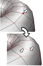
Chamfer box showing extruded vertex
Opens the Extrude Vertices caddy, which lets you perform extrusion via interactive manipulation.
If you click this button after performing a manual extrusion, the same extrusion is performed on the current selection as a preview and the caddy opens with Extrusion Height set to the amount of the last manual extrusion.
 Chamfer
Click this button and then drag vertices in the active object. To chamfer vertices numerically, click the Chamfer Settings button and use the Chamfer Amount value.
If you chamfer multiple selected vertices, all of them are chamfered identically. If you drag an unselected vertex, any selected vertices are first deselected.
Each chamfered vertex is effectively replaced by a new face that connects new points on all edges leading to the original vertex. These new points are exactly <chamfer amount> distance from the original vertex along each of these edges. New chamfer faces are created with the material ID of one of the neighboring faces (picked at random) and a smoothing group which is an intersection of all neighboring smoothing groups.
For example, if you chamfer one corner of a box, the single corner vertex is replaced by a triangular face whose vertices move along the three edges that led to the corner. Outside faces are rearranged and split to use these three new vertices, and a new triangle is created at the corner.
Alternatively, you can create open space around the chamfered vertices; for details, see Chamfer.
Opens the Chamfer caddy, which lets you chamfer vertices via interactive manipulation and toggle the Open option.
If you click this button after performing a manual chamfer, the same chamfer is performed on the current selection as a preview and the caddy opens with Chamfer Amount set to the amount of the last manual chamfer.
 Weld
Weld
Combines contiguous, selected vertices that fall within the tolerance specified in Weld Vertices caddy. All edges become connected to the resulting single vertex.
Weld is best suited to automatically simplifying geometry that has areas with a number of vertices that are very close together. Before using Weld, set the Weld Threshold via the Weld caddy. To weld vertices that are relatively far apart, use Target Weld instead.
Opens the Weld Vertices caddy, which lets you specify the weld threshold.
 Remove
Deletes selected vertices and combines the polygons that use them. The keyboard shortcut is Backspace.
Removing one or more vertices deletes them and retriangulates the mesh to keep the surface intact. If you use Delete instead, the polygons depending on those vertices are deleted as well, creating a hole in the mesh.
 Break
Break
 Target Weld
Allows you to select a vertex and weld it to a neighboring target vertex. Target Weld works only with pairs of contiguous vertices; that is, vertices connected by a single edge.
In Target Weld mode, the mouse cursor, when positioned over a vertex, changes to a + cursor. Click and then move the mouse; a dashed, rubber-band line connects the vertex to the mouse cursor. Position the cursor over another, neighboring vertex and when the + cursor appears again, click the mouse. The first vertex moves to the position of the second and the two are welded. Target Weld remains active until you click the button again or right-click in the viewport.
Sets the weight of selected vertices. Used by the NURMS subdivision option and by the MeshSmooth modifier. Increasing a vertex weight tends to pull the smoothed result toward the vertex.
 .
.
For instructions for using the caddy, see The Caddy Interface.
Toggles the availability of the Weight control on the The Caddy Interface when Select And Manipulate is active.
Certain modeling operations can leave unused (isolated) map vertices that show up in the Unwrap UVW editor, but cannot be used for mapping. You can use this button to automatically delete these map vertices.