Chapter 5, Getting Familiar with Your Workspace
| Player | Track Editor | ||
Chapter 5, Getting Familiar with Your Workspace |
|||
 Cycling through Inputs and Outputs
The Schematic is the view in which you build the dependency graph for a composition which is a set of connected nodes. You can set the direction in which processing proceeds in the User Preferences Creative tab. For 2D workflows, you can build the dependency graph in a left-to-right or top-down direction. For 3D workflows, you can build the dependency graph in a left-to-right or bottom-top direction--see Setting User Preferences.

 "Show full-size image")
| A dependency graph with a left-to-right flow. |

 "Show full-size image")
| A dependency graph with a top-down flow. |
When you create a new composition, the only node in the tree is the output node (every composition has only one primary output node). When you create a composition by importing media, the composition contains one input node (which points to the media you imported) and one output node. You then build the dependency graph by adding tool nodes.
Note: Nodes do not necessarily have to be connected. For example, you can create branches that you connect or disconnect to experiment with different scenarios.
When using super tools or working inside a grouped tool, the name of the tool or group is displayed at the bottom of the Schematic, so you always know where you are in relation to the dependency graph.

There are a number of different types of nodes, each represented by a distinct icon.
| Node icon: | Represents: |
|
An input node for footage. It is identified by a small film icon on the left of the proxy. The Link Image tab opens when a footage input node is selected in the Schematic view. |
|
An input node for a composition created during a media import. It is identified by a small sheet icon on the left of the proxy. When you select an imported media input node, the tool UI displays the Import Image tab. The input node displays a proxy of the media it references. |
|
An input node for a linked composition. It is identified by a small composition icon on the left of the proxy. When you select a linked composition input node, the tool UI displays the Link Image tab. The input node displays a proxy of the rendered output it references. |
|
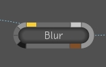
A normal tool node. |
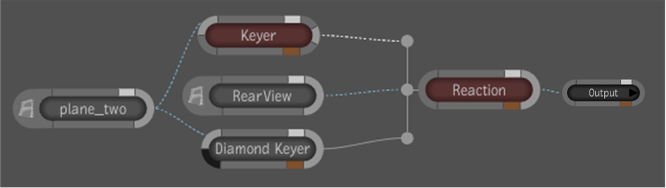
|
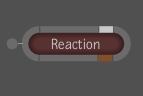
A super tool node. Each super tool can have its own icon. The Reaction super tool icon is shown here. A super tool node behaves as a group node in that you can enter the node to work with the tools it contains. |
|
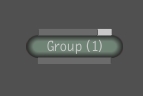
A group node that you create by selecting two or more nodes and grouping them together. You can right-click a group and select Edit Group to work only with the nodes in that group. |
|
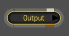
The primary output node for the composition. A dependency graph always has exactly one primary output node. You cannot delete this node, but you can add secondary output nodes to the composition--see Multiple Output Nodes. The output node represents the result of the composition. When you select this node, the tool UI displays the Output tab. The output node does not display a proxy of the result. |

|
A secondary output node for a composition. Note that secondary output nodes vary slightly in appearance from the primary input node, it is a lighter gray. |
A composition can support multiple output nodes which provide simultaneous renders from different points in the dependency graph. This characteristic of the composition lets you link to a composition at different points in the dependency graph.
An output node cannot be muted, however, intermediate results can be enabled on output nodes and output nodes can be grouped at any level. There's no restriction on the presence of an output node at the highest group level (the composition level).
Each output node has its own format (resolution, pixel aspect ratio, rate, channels and depth) and it crops its input image according to its format.
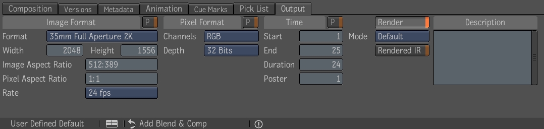
An output node has the following editable values. You can reset the values back to their defaults in the Tool Options area (Reset button):
 "Show full-size image")
| Value: | Description: |
| Name | Initialized to Output (#). |
| Description | Of arbitrary length, empty by default. |
| Image Format | Width, height, pixel aspect ratio and rate. Primary output is initialized from the composition project settings, additional outputs from the primary output. |
| Pixel Format | Channels and depth. Primary output is initialized from the composition project settings, additional outputs from the primary output. |
| Start | Start frame index. Primary output is initialized from the composition project settings, additional outputs from the primary output. |
| End | End frame index, exclusive. Primary output is initialized from the composition project settings, additional outputs from the primary output. |
| Duration | End - Start. |
| Poster | Frame used for proxies, defaults to start value. |
| As Primary Output Image Format | Whether the width, height, pixel ratio and rate values follow the primary output values. Always off on primary output. On by default on additional outputs. |
| As Primary Output Pixel Format | Whether the channels and depth values follow the primary output values. Always off on primary output. On by default on additional outputs. |
| As Primary Output Time | Whether the start, end and poster values follow the primary output values. Always off on primary output. On by default on additional outputs. |
| Render on/off | Whether the output is rendered upon a publish command, on by default. |
| Render mode | Render mode used upon a publish or render command. Set to the composition render mode project setting by default. |
One of the outputs is tagged as being the primary output. Aside from identifying the principal output of a composition, the primary output is most useful in the following workflows:
The composition start/end (in the timeline) and rate are dictated by the primary output start/end and rate respectively.
Composition format displayed in the Library Browser is driven by the format of the primary output.
Composition proxies shown in the Library Browser are generated from the primary output.
Player in Composition display mode shows the image results of the primary output node.
Comparison in the player against the composition refers to the primary output.
When linking to a composition, even though all outputs of the linked composition are represented on the link node, only the primary output socket is automatically connected to the destination graph.
When inserting a composition into another one, the input node of the primary output from the source graph is used as the connection point when the composition is dropped on an input socket in the destination graph.
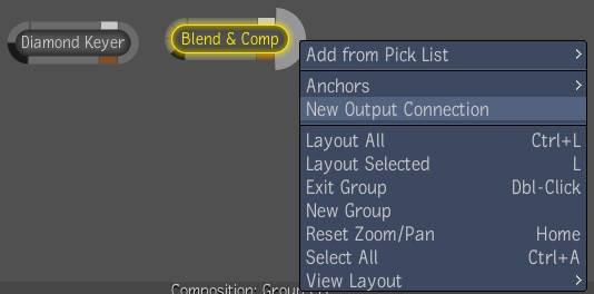
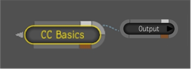
When dropping tools in the Schematic view, the south gate option Add Before Primary Output connects the new nodes before the primary output node.
Additional outputs are initialized (or reset) with the values of the primary output. Other outputs can also follow various sets of values from the primary output (image format, pixel format, time).
The first output node that is automatically created with a new composition is the primary output by default. However, in a composition with multiple outputs, any output can be set as the primary output at any time. This can be achieved through a drop-down menu listing the output node names in the Composition tab.
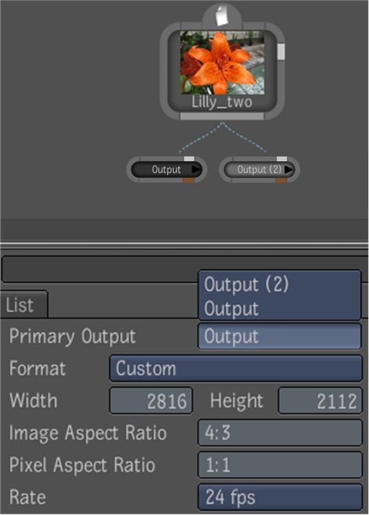
 "Show full-size image")
You can also use the Set As Primary right-click option on an output node in the Schematic view.

 "Show full-size image")
Creating a new composition automatically adds an output node to it. However, you can add more output nodes anywhere in the composition.
Do one of the following:
Drag the Output tool from the Utilities folder in the Tools tab and drop it into Schematic view.
If you have added the Output tool to a Pick List, right-click in the Schematic view and select the Output tool from the Pick List.
Select the Working composition from the Composition Browser, right-click and select the Output tool from the Pick List.
Select an output node in the Schematic view, right-click and select Copy, or press Ctrl + C. Then right-click again and select Paste or press Ctrl + V.
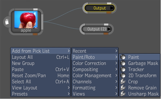
 "Show full-size image")
The primary output cannot be deleted, which ensures that a composition has at least one output. Graphical delete options on the primary output are absent and an attempt to delete it in any other way (hotkey or scripting) results in an error message.
Do one of the following
In the Schematic view, highlight the secondary output(s) you want to delete, right-click and select Delete or press the Delete key.
Highlight the secondary output node(s) you want to delete in the Composition Browser, right-click and select Delete.
Each node has a set of tabs around its outer edge. The name of each node appears either underneath it or inside it.
| Tab: | Description: |
| Input | You connect an input to this tab. If a node accepts multiple inputs, the tab is divided into the number of inputs the node
accepts. A node that accepts a single input:
|
| Output | Contains the output of the node. You create connections between nodes by connecting the output tab of one node to the input
tab of another. The Output node contains the result of the dependency graph. Note that you can connect an output to more than
one input. This is called "instancing" the node.
|
| Proxy | Click this tab (T hotkey) to show or hide the proxy for the node.
|
| Masking | An input for masking--see Pixel Masking.
|
| Intermediate Result | Click this tab to enable intermediate results for the node--see Creating Intermediate Results.
|
| Marked for keyframing icon | A yellow icon appears next to the image input tab when the tool has been marked for keyframing--see Marking Attributes for Keyframing.
|
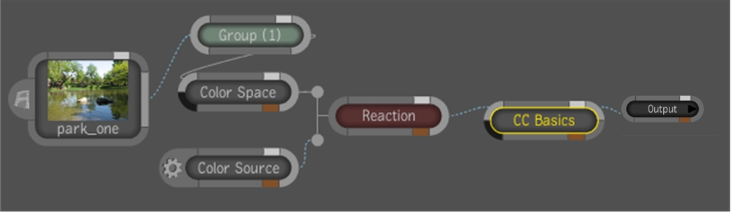
The connection lines in a dependency graph visually indicate by color and style what you are outputting: RGBA, RGB, or A. You can also choose how you want the lines to appear: curved, angled, or straight.
| Color | Line Style | Output |
| Gray | Solid line | RGBA |
| Light-blue | Dashed line | RGB |
| White | Dashed line | A |
 "Show full-size image")
Middle-click or press the tilde (~) key to display the drop gate, and swipe south to the Schematic Options.
Under Display, select an option from Links for the connection lines.

 "Show full-size image")
Note: You can also set the links style in your user preferences--see Setting User Preferences.
When working in the Schematic view, you can:
Show or hide the Schematic Navigator.
Clean up the view (clean up all or a portion of the dependency graph, automatically zoom to fit the dependency graph in the view).
Change the name of a node.
Work with connections (connect one node to another, insert a node between two nodes, disconnect one node from another, reposition a node within the dependency graph, change the appearance of connections, have connections highlight when you pass the cursor over them).
Work with groups and super tools (create a group, edit a group or enter a super tool, exit a group or a super tool, ungroup a group, add inputs and outputs to group nodes).
Work with branches (collapse or expand a branch).
Mute or unmute a node.
Turn intermediate results on or off for a node.
Set or clear a context point on a node--see Setting Context Points.
Reset the node to its default values.
Cut, copy, paste, or delete nodes.
Navigate nodes
Do one of the following:
To clean up the complete tree, right-click and select Layout All, or press Ctrl + L.
To clean up a portion of the tree, select the nodes to clean up, then right-click, and select Layout Selected or press L.
Right-click and select Reset Zoom/Pan or press Home.
Select the node to display its tabs in the tool UI.
In the Tool Options at the right, click in the Name field and edit the name.
Press Enter to accept your edits.
The node in the Schematic view updates to reflect the new name.
Press the D key and pass the cursor over a node. Shift + D will turn on all the node details without having to pass over the node.
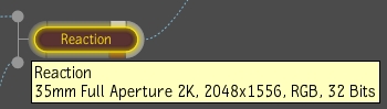
 "Show full-size image")
A tooltip displays the details of the selected node. If the node was renamed, the node's original name appears in the tooltip.
Select one or more nodes and do one of the following:
Right-click the node and select Thumbnail.
Press T.
Do one of the following:
Click the output of a node and drag to the input of another node (or click and drag from the input area of one node to the output area of another). A gray connection line appears as you drag. Release to create the connection.
Press Shift and drag one of the nodes to the other, so that the output area of one node brushes, or "kisses", the input area of the other. A connection line appears when the two nodes kiss. Release to establish the connection. If you want to cancel the operation, release Shift as you continue to drag.
Note: There are hotspots located along each edge of the viewer to be used to auto-pan the viewer when holding the cursor down over these areas for a predetermined time. This will be used when dragging or connecting nodes. The speed at which the panning is done can be controlled by using the Ctrl hotkey to speed up panning or the Alt hotkey to slow down panning.
Press Alt and drag the node you want to insert onto the connection line between the two nodes, then release. If you want to cancel the operation, release Alt as you continue to drag.
Do one of the following:
Press Ctrl and drag the cursor (scissors icon) through the connection.
Right-click the connection line between the nodes and select Disconnect.
Hold down the Ctrl key, click one end of a connection link to break the link. Drop the link on a different node.
Do one of the following:
Disconnect the node and then connect it in a new position.
Press Alt and drag the node to a new position in the tree, then release. The connection lines adjust to disconnect the node from its previous neighbors and connect it in the new position.
Display the Pick List, Tools, and Views tab by middle-clicking or pressing the tilde (~) key. Drag and drop a tool onto the selected node.
A drop gate appears.
Swipe through the Replace option.
The selected node is replaced with the new tool.
Select the nodes you want to group, right-click one of the nodes and select Group or Group (Visual). You can also press G for Group or Shift+G for Group (Visual).
Note: If more than one node is selected, they will be grouped. If there is only one node selected and it is not a group node, it is grouped, otherwise if it is a group node, it is ungrouped.
When you create a visual group node, all the nodes in this group display semi-transparent backgrounds, which allows the nodes to adopt the color of the visual group itself. Nodes which are not part of the visual group that are dragged over the group will stand out because they will be a different color from the nodes in the visual group.
Visual group nodes are created with a default color. However, by right-clicking on the title bar of the visual group, you can select the Color option, which will display a color picker that allows you to choose a new color.
A new node-independent tab is created in the Tool UI for the group node. By default, it will be named "Group (#)," for example, "Group(1)." You can rename the group tab by entering a new name in the Name field in the Tool Options area.
Right-click the group node (to edit a group) or the super tool (to enter the super tool) and select Edit Group, or double-click the node.
The Schematic view updates to display the nodes in the group or the nodes of the super tool.
Right-click in the Group Schematic view and select Exit Group, or double-click the background.
To add a node to a visual group node, press V and then drag the node into the group node.
To remove a node from the visual group node, press Shift + V and drag the node out of the group node.
The size of the visual group node is determined by the location of the contained nodes. The size of the visual group node will expand or contract as the contained nodes are moved around.
To move a visual group node, drag the title bar of the group node.
Right-click on the title bar of a visual group node and select Lock, which locks the group node, as well as all the nodes inside the group. This means that all the nodes inside the group, as well as the group itself, are locked in place.
To lock just the nodes inside a group, while still allowing the group itself to be moved, right-click on the title bar of the visual group node and select Lock Tools.
To open a group node, right-click on the node and select Open or press Shift+O. Opening a group node displays the contents of the group node while applying the visual group attribute.
To close a group node, right-click on the title bar of the group node and select Close or press Shift+C. Closing a group node removes the visual attributes of the node and collapses it back to its regular appearance.
Right-click the group node or the title bar of the visual group node and select Ungroup, or press G.
Do one of the following:
Enter the group node by double-clicking the node, then drag the link from an input or output beyond the top border of the schematic. Control will be transferred to the group level one up in the hierarchy. At this point, releasing beyond the border will create a connection node. Moving within the border will allow connection to another node. If this group level is not the top most, moving within the border and back up again will transfer control to the next group up in the hierarchy. Moving down in the group hierarchy is accomplished by dragging beyond the bottom border of the Schematic view. All dragging must be done in conjunction with the Shift hotkey.
Enter the group node by double-clicking the node, then right-click and select New Connection. Note that the cursor must be over an input or output.
 "Show full-size image")
Locate the node at which you want to collapse the branch.
Right-click the node and select Expand or Collapse or press E.
The branch leading into that node collapses. The arrow on the left of the node indicates a collapsed branch.
 "Show full-size image")
| Expanded branch |
 "Show full-size image")
| Collapsed branch |
Right-click the node containing the collapsed branch and select Expand or Collapse or press E.
| Node containing a collapsed branch |
| Expanded branch |
Select the node.
Right-click a node and select Mute or Unmute, or press M.
Note: You can also mute/unmute a node by selecting it and clicking the Mute button in the Tool Options area. This button is located to the left of the Reset button.
Do one of the following:
Press X and click a node.
Right-click and choose Select Upstream.
All nodes upstream are selected.
Hint: You can select multiple branches without clearing the selection.
Click the orange tab in the lower-right of the node.
The orange tab brightens or darkens to indicate intermediate results are respectively, on or off for the node--see Creating Intermediate Results.
Note: You can also turn intermediate results on/off for a node by selecting the node and clicking the IR button in the Tool Options area.
Press the number of the context point you want to set and click the node on which you want the context point, or right-click the node and select Context # (Set). For example, to set context point 3, press 3 and click the node.
The number of the context point, preceded by the letter C (for example C3 for context point 3), appears to the left of the node name and a broken green line appears around the center of the node.
Note: If you set more than one context point on a node, the numbers of all context points set on the node appear after the C. For example, C134 indicates you set context points 1, 3, and 4 on the node.
Press the number of the context point you want to clear and click the Schematic background or right-click the node and select Context # (Remove).
The context point label (for example C4 for context point 4) is deleted along with the broken green line around the center of the node.
Right-click the tool node you want to reset and select Reset, or press Ctrl + R.
Note: You can also reset a node by selecting it and clicking the Reset button in the Tool Options area.
Select the node(s) you want to cut or copy.
Do one of the following:
To cut the node(s), right-click one of the selected nodes and select Cut, or press Ctrl + X.
To copy the node(s), right-click one of the selected nodes and select Copy, or press Ctrl + C.
To paste the cut or copied node(s), right-click outside all nodes and select Paste, or press Ctrl + V.
Select the node or nodes you want to delete.
Do one of the following:
Right-click one of the nodes and select Delete, or press Delete.
Drag a reasonable distance outside the bottom edge of the Schematic view and release.
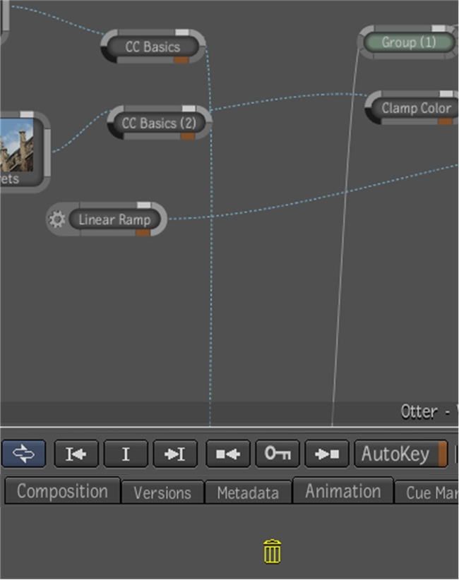
 "Show full-size image")
Note: You can also delete nodes by selecting them and clicking the Delete button in the Tool Options area of the tool UI.
Do one of the following:
Right-click the Schematic view and choose Select All.
Press Ctrl + A.
All nodes and connection lines are selected in the Schematic view.
Drill-Down is a way to change the currently selected node without depending on a viewer, such as the Schematic view or the Composition browser. It changes the current node by navigating upstream (towards inputs) or downstream (towards outputs) using hotkeys. It only allows navigating through connected nodes.
Do one of the following:
Press Alt + Shift + Left arrow to select the upstream node connected to the current node's primary input.
Press Alt + Shift + Right arrowto select the first downstream node connected to the first output.
Press Alt + Shift + Down arrowto select the next node for the last direction taken. For example, after pressing Alt + Shift + Left arrow to go towards the primary input, pressing Alt + Shift + Down arrow will select the node on the second input. It works similarly for outputs: pressing Alt + Shift + Down arrow will visit the next node connected the output, or go to the next output, whichever applies.
Repeatedly press Alt + Shift + Down arrow to cycle through the candidates in their order of presentation.
Press Alt + Shift + Up arrow to select the previous candidate for the last direction taken, following the same logic as for Alt + Shift+ Down arrow.
For easy display of a node's multiple inputs and outputs in the Player, you can cycle the hotkeys. When in tool input mode in the Player, pressing the 5 hotkey a second time cycles to the next image input and cycles back to the first image input. When in tool output mode in the Player, pressing the 6 hotkey a second time cycles to the next image output and cycles back to the first image output. These hotkeys can be used to cycle through composition outputs and rendered results.
For added flexibility, you can assign a context point to a tool node. For example, while viewing the output of a tool in one Player, you may also want to view the result of a composition, matte, or other Keyer super tool output in another Player. To do this, add a context point (C1, C2, C3 or C4) to the Keyer super tool and assign a Player view to that context point. Then, use the context point's hotkey number (1, 2, 3 or 4) to cycle through the Keyer's outputs--see Setting Context Points.
You can set a number of display and playback options for the Schematic view.
With the cursor over the Schematic view on which you want to set options, middle-click or press the tilde (~) key and go through the south gate.
The settings for that Schematic view are displayed.
Select the Display tab.
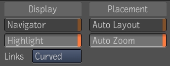
 "Show full-size image")
Set the Display options:
| Select | To |
| Navigator | Show or hide the Schematic Navigator. By default, the Navigator is displayed. |
| Highlight | Expand and highlight the tabs of a node when you pass the cursor over them. |
| Links | Change the line style of connections. Lines can appear as: Curved, Straight, or Angled. |
Set the Placement options:
| Select | To |
| Auto Layout | Automatically organize all of the nodes in the dependency graph. |
| Auto Zoom | Automatically zoom to keep the complete dependency graph visible in the center of the Schematic view. |
Note: You can make any of the display setting the default setting for the view by selecting them in your user preferences--see Setting User Preferences.
Middle-click or press the tilde (~) key to display the drop gate, and swipe north to view the full screen Schematic.
Middle-click or press the tilde (~) key to display the drop gate, and swipe south to the Schematic Options.
Under Display, select Navigator to hide the Navigator. By default, the Navigator is visible.
Select the Playback tab.
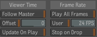
 "Show full-size image")
Set the Viewer Time options.
Follow Master -- Sets the view to global time. Disable to use its own local time.
Offset -- Lets you set a frame offset for the time. The frame offset is with respect to the time you set for the view. For example, if you set a frame offset of 5 and selected the Follow Master option, the proxy in the view always displays the frame that is five frames ahead of the frame currently running in global time. If you deselected Follow Master, the proxy in the view always displays the frame that is five frames ahead of the frame running in the local time of the view.
Update on Play -- Updates the proxy at each frame when you play the composition. Deselect to update the proxy only when you stop playing the composition, and only at the scrub frames when you scrub through the composition.
Set the Frame Rate options.
Play All Frames -- Plays all frames in the composition, regardless of whether it maintains the frame rate set for the composition. Deselect to have the view maintain the frame rate for the composition, at the expense of dropping frames where necessary.
User -- Lets you set the frame rate at which you want the Schematic view to play the composition. Type the frame rate in the field to the right of this button, or click and drag on the bottom edge of the field to adjust the value.
Stop on Drop--Stops the Player if a tool is dropped into the dependency graph.
Things to Remember
Each Schematic view has its own set of options except for the flow, (left-right, top-bottom, etc.).
 "Show full-size image")
 "Show full-size image")
 "Show full-size image")
 "Show full-size image")

 "Show full-size image")
 "Show full-size image")
 "Show full-size image")