User Guide > General > Paint Effects and 3D Paint > Paint Effects and 3D Paint Windows
and Editors >
Paint Effects Brush Settings
These are the attributes in the opening section of the Paint Effects Brush Settings window.
Brush Type
Select the type of brush you want to paint with. All brush types use the shape defined by the brush attributes.
Distorts paint already applied to the canvas or scene. If the stroke uses fake shadowing (see Fake Shadow), the shadows also smear.
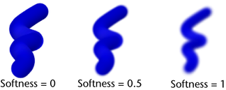
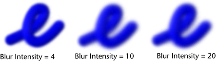
Softens the look of paint already applied to the canvas or scene. If the stroke uses fake shadowing (see Fake Shadow), the shadows also blur.
In the canvas, the Erase brush removes the color from the painted pixels, revealing the underlying canvas Clear Color and maintaining the shape of the brush. For details, see Erase paint from the canvas.
In the scene painting view, the Erase brush replaces the pixel color of the paint stamps it overlaps with black (alpha 0).
When you erase, the alpha values are lowered, rather than increased, which means you can use the Erase brush to erase holes in a texture or scene.
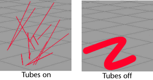
The ThinLine type of brush allows you to render large numbers of fine tubes much more quickly than the Paint brush type. It uses a direct anti-aliased line draw rather than a series of brush stamps. The Multi Streaks method is also available when the ThinLine brush type is used. In combination with the Multi Streaks method, the ThinLine brush type can be up to 100 times faster for hair than the Paint brush type with better line detail. In addition, new looks are possible using the Multi Streaks, such as wet clumping hair.
Renders Paint Effects using triangulated tubes instead of brush stamps. This results in accurate conical geometry with textures that correctly map on the surface. Flat surfaces are rendered more accurately than when the Paint Brush Type is used. While the Paint Brush Type is generally better when representing soft, fuzzy volumes, the Mesh Brush Type is better at hard surfaces.
With the Mesh Brush Type you can create Paint Effects trees and plants that are convincing not just from a distance, but also close-up. You can also create shapes, such as hard-edged geometry (buildings) and do per-pixel lighting on the mesh (including specular highlights). There is also a built-in environment map on the brush that is useful when simulating reflective surfaces (see Mesh Environment Reflections). We’ve added displacement and bump mapping to enhance the detail of the mesh surface (see Set mesh displacement/bump mapping). The triangles are not kept in memory, but rather generated at render time. As a result, you can use a lot of triangles without running out of memory.
These are the options in the Channels section of the Paint Effects Brush Settings window.
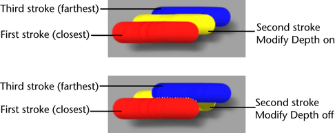
Turn on Depth to create a depth channel. Strokes appear on top of previously painted strokes when Depth is off.
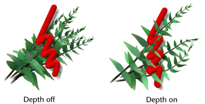
In the scene, turn on Depth for more realistic natural effects (for example, for plants, fire, water). This should also prevent unusual results. By default, depth is forced on in the scene (see Force Depth).
These are the options in the Brush Profile section of the Paint Effects Brush Settings window.
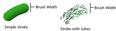
Defines the width of the brush in Maya working units. For simple strokes, the brush width defines the width of the paint stamps applied along the stroke path. For strokes with tubes, the brush width defines the stroke path boundary—tubes can start growing only within the path defined by the brush width. The Paint Effects Tool cursor is a brush stamp outline. The Brush Width is represented by the diameter of this outline.
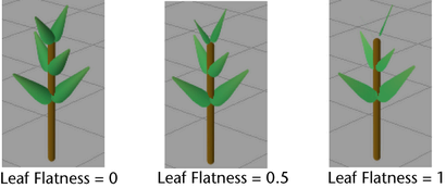
For simple strokes, Flatness1 defines how flat the paint lies along the stroke path. When Flatness1 is 0, the paint is applied to the stroke as if you squeezed it out of the tube. The stroke appears raised from the side. When Flatness1 is 1, the paint lies flat on the surface as if you removed the excess paint.
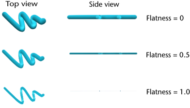
For strokes with tubes, Flatness1 and Flatness2 define how flat each tube is at its base and at its tip, respectively. The values between the base and tip are linearly interpolated.
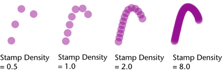
Paint is applied to strokes in overlapping stamps. If the stroke is simple (it has no tubes), the stamps are applied along the stroke path. If the stroke has tubes, the stamps are not applied along the stroke path, but are applied along the tube paths. Stamp Density defines the number of stamps to apply along the paths, relative to the Brush Width or Tube Width. For example, if you set Brush Width to 2, and Stamp Density to 8, then every two units of path would have 8 stamps on it (as long as the brush width remains constant). Similarly, if you set Tube Width2 to 2, and Stamp Density to 8, then every two units of tube would have 8 stamps on it (as long as the tube width remains constant).
If you set Stamp Density to 1, the paint path will look like a line of circles that just touch on the edge. If you set Stamp Density to be greater than one, the circles will overlap by a factor of their width (for example, if Stamp Density is 2, the stamps will overlap by half their width). If you set Stamp Density to be less than one, there will be spaces between the stamps.
(Primarily for toon shader use.) This is only for Stamp draw mode. Occlusion Width Scale reduces the stamp size based on the overlap by foreground objects. The full stamp is always drawn, avoiding antialias problems where occluded by non-Paint Effects foreground objects. When the entire stamp is occluded the size of the stamp is reduced to zero, and therefore hidden.
When Edge Clip is turned on, you can make 3D strokes render flattened as 2D, as if they are painted directly onto a surface's texture. The Edge Clip Depth attribute controls how far in front of a surface the stroke can be before it becomes invisible. Therefore 3D strokes that sit close to an object’s surface can be seen if the surface is behind them, but not if the surface edge is in profile. You could use Edge Clip for drop shadows and to fake shadows.
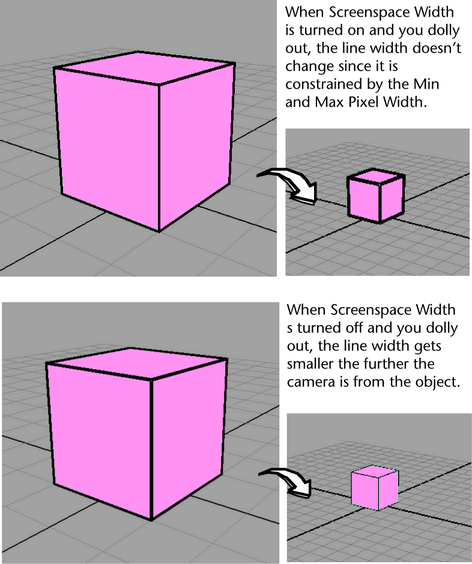
These are the attributes in the Screenspace Width Control subsection of the Brush Profile section of the Paint Effects Brush Settings window.
When Screenspace Width is turned off the Paint Effects lines (brush strokes) appear thinner the further they are from the camera. But when it’s turned on, there is no difference in the Paint Effects line width no matter how near or far the line is from the camera; with Screenspace Width turned on, the Min and Max Pixel Widths are respected.
Turn this option on to maintain the brush width at all depths in the scene. This option is useful in scenes where you want cartoon-like outlines that retain a fixed width.
The brush stroke width is normally in worldspace and it appears to be constant in the 3D world. Screenspace refers to the flat 2D world of the rendered image (like a paint canvas). When the width is defined in screenspace it is relative to the overall size of the image, and the width is constant despite the distance of the object. Distance Scaling allows you to blend between the two width methods.
The Paint Effects display in the scene view updates when Screenspace Width is turned on, so you can display screenspace width Paint Effects lines in realtime.
These are the Paint Effects Brush Settings in the Twist section of the Paint Effects Brush Settings window.
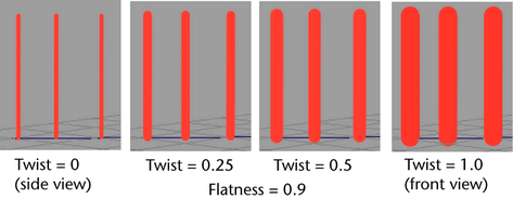
Tubes can twist around their own axes as they grow. The Twist attribute defines the initial twist value. Twist is only noticeable when the tubes have some flatness or texture (Flatness1 and Flatness2 values are greater than 0). See also Twist Rate.
When Forward Twist is turned on, the broad or flat side of tubes are always oriented towards the camera. Textures are similarly affected so that they always face the camera. This is particularly useful when the Flatness is 1, as you can use billboard textures to minimize geometry. For leaves, you could use a texture of a large clump of leaves with alpha on flat leaves. Turning on Leaf Forward Twist (Tubes > Growth > Leaves) would ensure that the broad side of the textured leaf clump is rotated towards the view so it always looks full. Another example might be to use the image of an apple with alpha on a flat flower petal. Turning on Petal Forward Twist (Tubes > Growth > Flowers) twists the petal to face the view so the apples do not look flat from some angles. The simplest way to represent a tree is an image of a tree with alpha textured to a billboard facing the camera. The following settings can be used to set up this type of billboard:
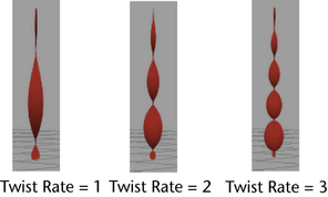
Defines how much tubes twist along their length. Twist is noticeable only when the tube has some flatness or texture (see Flatness1, Flatness2and Map textures to color and opacity.)
These are the options in the Thin Line Multi Streaks section of the Paint Effects Brush Settings window. For more information, see Set Thin Line Multi Streaks.
These are the options in the Mesh section of the Paint Effects Brush Settings window. For more information, see Set mesh attributes.
This affects the lighting of the object and makes the edges around tubes hard when using the Mesh Brush Type. For example, if the tube sections are set to 4 and Hard Edges is turned on, it will make the tube shade as if the 4 sides are flat, rather than trying to simulate a rounded tube. For bends in the direction of the tube, for example, due to changes in the Width Scale, the bend angle across a given must be sufficiently large to make the angle hard. The number of segments used can affect whether a given region on the tube becomes hard edged or not. This attribute adjusts the normals used for shading and does not alter the shape of the tube. This is off by default.
The Thorns on Mesh section is a subsection of the Mesh section. These are the Paint Effects Brush Settings in the Thorns on Mesh section that can be used to control the look and size of the thorns. For more information, see Set mesh thorn attributes.
The Mesh Environment Reflections section is a subsection of the Mesh section. These are the Paint Effects Brush Settings in the Mesh Environment Reflections section. For more information, see Set mesh environment reflections.
These are the options in the Shading section of the Paint Effects Brush Settings window.
On simple strokes, Color1 defines the basic color of the paint. On strokes with tubes, Color1 defines the color of the tube roots. Click the Color1 color box and select the stroke color from the Color Chooser. Use the slider to adjust the color value. Color1 is used only if Map Color (under Texturing) is turned off.
See also Color Length Map.
Makes the paint look incandescent—as if it were illuminated from its own internal light. On simple strokes, this attribute defines the incandescence for the stroke. On strokes with tubes, this attribute defines the incandescence of the tube roots.
Click the Incandescence1 color box and select the incandescence color from the Color Chooser. Use the slider to adjust the incandescence value. The higher the value, the more incandescent the paint is. When the value is 0 (black), there is no incandescent effect, when the value is 1 (white) or the color is pure, the effect is strongest.
See also Incand Length Map.
Defines the opacity of the paint. On simple strokes, Transparency1 defines the opacity for the stroke. On strokes with tubes, Transparency1 defines the opacity of the tube roots.
Click the Transparency1 color box and select the transparence color from the Color Chooser. Use the slider to adjust the transparency value. The higher the value, the more transparent the paint is.
When the value is 0 (black), the paint is fully opaque, or “solid”. When the value is 1 (white), or a pure color with a value of 1, the paint is transparent.
Transparency1 is used only if Map Opacity (under Texturing) is turned off.
See also Transp Length Map.
The Tube Shading section is a subsection of the Shading section. These are the Paint Effects Brush Settings in the Tube Shading section.
Color2 defines the color of the tube tips. Click the Color2 color box and select the tube tip color from the Color Chooser. Use the slider to adjust the color value. Color2 is used only if Map Color (under Texturing) is turned off.
See also Color Length Map.
Makes the paint on tube tips look incandescent—as if it were illuminated from its own internal light.
Click the Incandescence2 color box and select the incandescence color from the Color Chooser. Use the slider to adjust the incandescence value. The higher the value, the more incandescent the paint is. When the value is 0 (black), there is no incandescent effect, when the value is 1 (white) or the color is pure, the effect is strongest.
See also Incand Length Map.
Defines the transparency (or opacity) of the tube tips. This is a color, so you can set the transparency of the R, G, and B channels separately. The closer to black each channel is, the more opaque it is.
Click the Transparency2 color box and select the transparence color from the Color Chooser. Use the slider to adjust the transparency value. The higher the value, the more transparent the paint is.
When the value is 0 (black), the paint is fully opaque, or “solid”. When the value is 1 (white), or a pure color with a value of 1, the paint is transparent.
Transparency2 is used only if Map Opacity (under Texturing) is turned off.
See also Transp Length Map.
These attributes define how much random variation Maya applies to tube colors when creating new tubes. When the values are low, all tubes are created using colors very close to Color1 and Color2. Increasing these values causes more random variation. You can control randomness of the Hue, Saturation, and Value individually.
Defines how much random variation in tube brightness there is. If the value is 0, all the tubes are created at the same brightness. As this value increases, the tubes are randomly assigned different brightnesses, with the amount of variation increasing. This is useful for creating effects like hair, where the individual strands should have some variation in brightness as they shadow each other.
These are the options in the Texturing section of the Paint Effects Brush Settings window.
By default, Transparency1 and Transparency2 are used to define opacity. Turn this option on to apply a texture to the opacity using the current texture. See Texture Type.
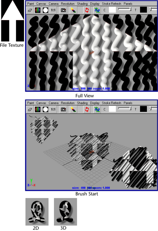
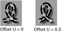
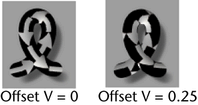
This option is used only when Map Color or Map Opacity is turned on. Select the type of texture you want mapped to Color and Opacity. You can map Checker, U Ramp, V Ramp, Fractal, and File type textures. For more information on mapping file type textures, see Map file textures to color and opacity.
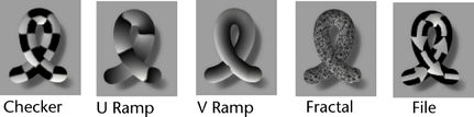
If you select Fractal, you can set the Fractal Amplitude, Fractal Ratio, and Fractal Threshold in this section.
If you select File, you can select the file in the Image Name box and select Frame Extension and Fringe Removal options.
The mapping is in “eyespace,” similar to Full View, but the position, scale, and offset of the texture is based on where the brush stroke starts. This texturing technique works best in scenes with Paint at Depth turned on for the brush. If the brush stroke starts far away in the scene, the texture is small. The closer the brush stroke starts, the larger the texture.
Defines the first color/transparency used by the selected Texture Type. For example, this could be one of the checker colors, or the color at the start of a ramp.
This texture color value is multiplied by the brush color value, Color1. So if Color1 is black (value 0), Tex Color1 will paint as black. To ensure that the painted texture colors match the texture colors set for the brush, set the brush color (Color1) to white (value 1) or set Tex Color Scale to 0.
Defines the second color/transparency used by the selected Texture Type. For example, this could be one of the checker colors, or the color at the start of a ramp.
This texture color value is multiplied by the tube tip color value, Color2. So if Color2 is black (value 0), Tex Color2 will paint as black. To ensure that the painted texture colors match the texture colors set for the brush, set the tube tip color (Color2) to white (value 1).
Turn this option on when you are animating a texture. Paint Effects replaces the frame number in the image name with the frame number in the Frame Extension box. For details, see Animate textures on strokes.
These are the options in the Illumination section of the Paint Effects Brush Settings window.
Turn on Illuminated so that lighting has an effect on the appearance of the stroke paint. You can use the lights in your scene to illuminate strokes or you can use a Paint Effects light. See Real Lights, next.
If Illumination is turned off, then strokes are painted in the colors you specify, with no shaded areas or specular highlights, even if there are lights in the scene.
By default, Illuminated and Real Lights are forced on in the scene in the Paint Effects Globals (see Force Real Lights).
This option is available only when Illuminated is turned on. Turn on Real Lights to use the lights in the scene to determine the position of shading and specular lights on the paint.
Turn off Real Lights to use a directional Paint Effects light. You can define its direction in the Light Direction attribute, but you cannot modify any other attributes (for example, intensity). When this option is turned off, lights in the scene have no effect on the paint.
By default, Illuminated and Real Lights are forced on in the scene in the Paint Effects Globals (see Force Real Lights).
This attribute is useful for creating a thick/thin effect for line modulation. Lighting Based Width controls the degree to which the line (tube) width is modulated by the light intensity. Brighter regions will be thinner, whereas shadowed and dark regions will have full width lines (tubes). Using negative values can have the reverse effect. The lighting used is a diffuse illumination that is relative to the local surface normal painted on by the stroke.
This setting is available only when Illuminated is turned on. The Translucence value controls how much the paint transmits and diffuses light. Light shining on the back of translucent paint can light up the front, although you still may not be able to see through it. To make the paint completely opaque, set this to value 0. To allow more light to diffuse through, set the value closer to 1.
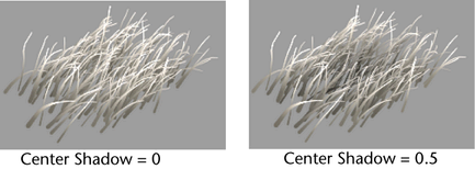
These are the options in the Shadow Effects section of the Paint Effects Brush Settings window.
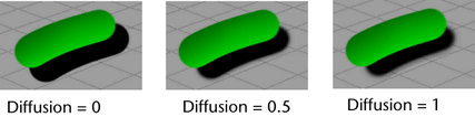
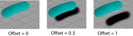
By default, all tubes are painted at the same brightness. This setting shades tubes closest to the centre of the stroke path, simulating the effect of a clump of plants where the plants on the outside are illuminated, but the plants on the inside are shaded because the light is blocked by the outside plants. Higher values make the shading darker.
Depth Shadow Type
This setting is used only when Depth Shadow is greater than 0. Select one of the following options:
Turn on Cast Shadows to make strokes cast shadows. Then select the light in the scene that you want to produce the shadows and in the Depth Map Shadow Attributes section of the light’s Attribute Editor, turn on Use Depth Map Shadows. The shadows will not appear when you refresh the scene painting view. They are created when you do a post-process render of the scene.
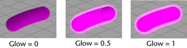
These are the options in the Glow section of the Paint Effects Brush Settings window.
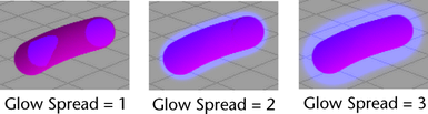
Defines the brightness of the standard glow, which is produced by applying paint stamps. A value of 0 produces no glow. Higher values add more glow. This glow effect is less effective on strokes with textures, but adequately adds glow to effects like stars. For more realistic glow, see Shader Glow.
Defines the brightness of the Shader Glow. It is more realistic than standard glow, and appears only when you perform a post-process render. It is useful for strokes with textures and effects like fire. To modify the Shader Glow attributes, double-click the shaderGlow icon in the Post Process folder of Hypershade. For information on these attributes, right-click the down arrow on the node icon and select Help on “shaderGlow”.
These are the options in the Tubes section of the Paint Effects Brush Settings window.
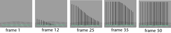
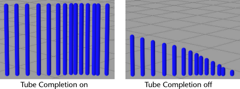
As you paint the stroke, Paint Effects samples points on the stroke path based on input from your mouse or stylus. When it samples a point, Paint Effects plants new tubes along the path between the last sampled point and the current one, then grows the previously planted tubes one more segment. When you finish painting the stroke, one of two things happens:
These are the Paint Effects Brush Settings in the Tubes > Creation section.
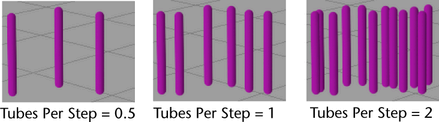
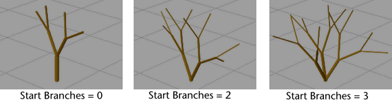
Defines the number of tubes that are planted at the first point of each path you draw. If you set Tubes Per Step to 0, you can use this setting to create a single object along the path. For example, set Tubes Per Step to 1 to form the trunk of only a single tree for every stroke, or set it to 100 to create a sunrise or spot glow effect.
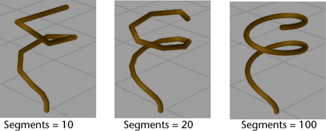
Defines the maximum number of segments a tube can have. Since tubes each grow one segment during each step in the growth simulation, the number of segments defines the “life span” of the tube. If you increase Segments, the tube length remains the same, but the segments making up each tube become smaller. Segments are straight, therefore more segments make the tubes appear smoother and less jointed.
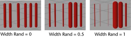
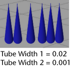
These settings define the width of the tubes at the base (Width 1) and at the tip (Width 2). The tube width changes linearly between these two values.
See also Width Rand and Width Bias, and Width Length Map.
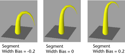
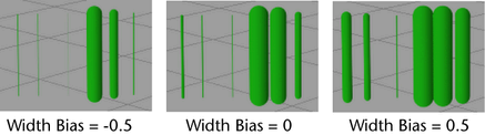
This setting is used only when Width Rand is greater than 0. It defines how the random widths are distributed. If Width Bias is 0, then there will be just as many wider tubes as there are thinner tubes. If Width Bias is a positive value, then there will be more wider tubes created than thinner ones. If Width Bias is a negative value, then there will be more thinner tubes created than wider ones. If you are creating plants, negative values give the most realistic results. (For each larger plant, there are usually a number of smaller plants.)
Defines how segments are distributed by length. If Segment Length Bias is 0, all tube segments are the same length. If the value is positive, segments closer to the base are longer. If the value is negative, segments closer to the tip are longer. The value represents the proportion of segments that are longer.
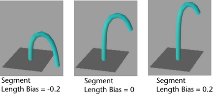
If Length Flex (see Length Flex) is set to 1, the segments are infinitely stretchy, therefore this setting has no effect.
This allows you to use a graph to control the width from base to tip of tubes, rather than using a simple linear interpolation between two values. When combined with the Mesh Brush Type you can define shapes like spheres, as well as control the profile of a tube. Width Scale is applied as a scale to the current width and defaults to 1.0 so that previous presets work with it.

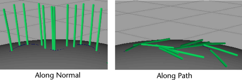
Tube Direction
Select what you want the primary axis to be to generate tubes.
Tubes are generated along the surface normal or the normal defined for the stroke (see Use Normal).
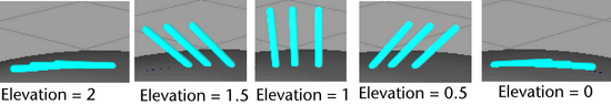
Imagine you are standing on a paint path, pointing straight ahead in the direction of the path. Moving your pointing hand straight up and down is like changing the elevation of your arm. These attributes define the range of possible elevations for tubes to lie. When both values are 1, tubes stand straight up (90 degrees, normal to the surface). When both values are 0, tubes lie flat along the path (0 degrees, tangent to the surface). When both values are 2, tubes lie flat along the path opposite to the path direction (180 degrees, tangent to the surface).
Elevation is the same as Inclination in Maya Fur.
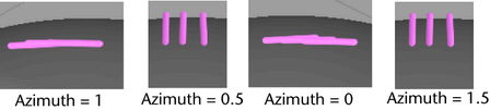
As with Elevation, imagine standing on the paint path, pointing straight ahead in the direction of the path. Rotating your body left and right is like changing the azimuth of your arm. These attributes define the range of possible angles for tubes to rotate around the normal axis. When both values are 0, tubes point along the path direction. If both Elevation Min and Elevation Max are 1, Azimuth values have no effect.
Azimuth is the same as Polar in Maya Fur.
These are the Paint Effects Brush Settings in the Tubes > Growth section.
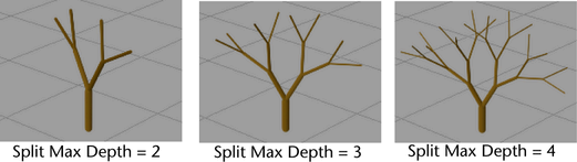
Turn this option on to split tubes into branches. See Set branch attributes.
Turn this option on to grow twigs on tubes or branches. See Set Twig attributes.
Turn this option on to grow leaves along tubes or branches. See Set leaf attributes.
Turn this option on to grow flowers along tubes or branches. See Set flower attributes.
Turn this option on to grow buds at the tips of branches and leaves. See Set bud attributes.
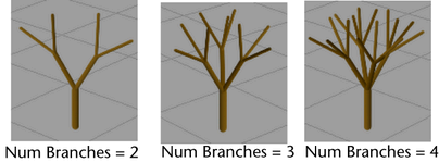
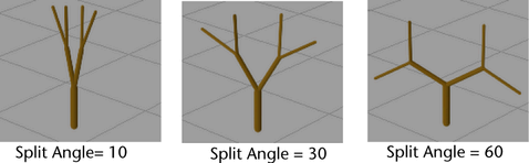
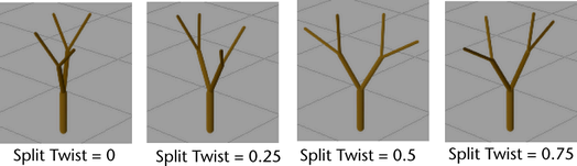
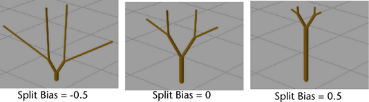
These are the Paint Effects Brush Settings in the Tubes > Growth > Branches section.
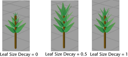
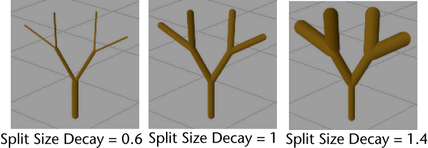
Defines the tube size factor applied at each branching. If the value is 1, then the branches are the same size as the branch they branched from. If the value is less than 1, the branches are smaller than the branch they branched from (like on a real tree). If the value is greater than 1, the branches are larger than the branch they branched from.
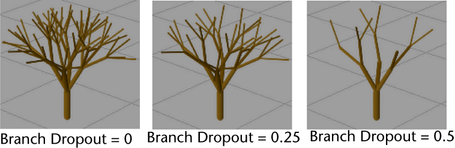
Defines the minimum size a tube must be to be “pruned.” If a tube is smaller than this size, it will not be pruned. See Branch Dropout.
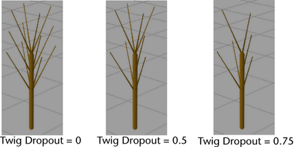
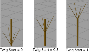
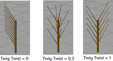
These are the Paint Effects Brush Settings in the Tubes > Growth > Twigs section.
These settings define the width of the twigs at the base and tip, respectively. The twig width changes linearly between these two values.
Twig width is a factor of the width of the branch that the twig grew from. For example, if you set Twig Base Width to 0.8, then the width of the base of the twig will be 0.8 times the width of the branch at the point where the twig emerged.
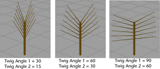
These settings define the range of angles that the twigs will make with their source branch. The first twig cluster created (closest to the root) uses Twig Angle 1, and the last twig cluster created (closest to the tip) uses Twig Angle 2. The angles of the twig clusters change linearly in between these two clusters.
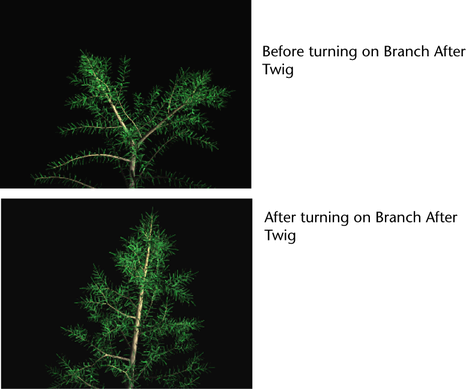
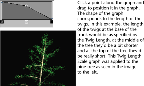
Turn this on to put branches on twigs rather than twigs on branches. If Branch After Twigs is turned on, then twigs are evenly distributed along the main trunk and branches split after the twig. The splitting defined by the branch attributes will occur on the twigs. This is useful in helping define many common tree shapes, such as pines. You can have a central trunk with multiple branches splitting off of it. You can also use Twig Length Scale to adjust the overall profile of the tree. From the twigs' starting point, it controls the density of the twigs and branches along the main trunk. Shorter twigs are adjusted to have fewer branching events and segments.
The base length of twigs is defined by the Twig Length attribute. However you might want twigs at the tip of a trunk to be shorter than ones at the base. The Twig Length Scale attribute allows you to scale the Twig Length: when it is set to 1.0 then the twigs will equal the Twig Length value, when it is set to 0.5 the twigs will be half the Twig Length value, etc. The horizontal dimension of the graph corresponds to the position from root to tip of the tube from which the twigs sprout.
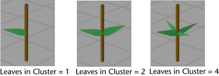
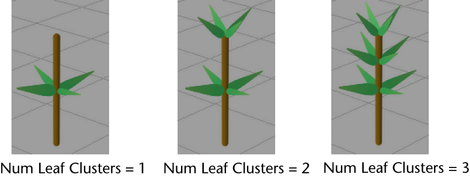
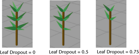
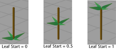
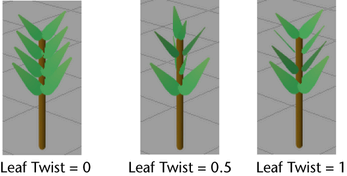
These are the Paint Effects Brush Settings in the Tubes > Growth > Leaves section.
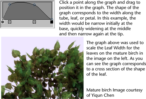
This allows you to use a graph to control the width from base to tip of leaves, rather than using a simple linear interpolation between two values. When combined with the Mesh Brush Type you can define shapes like spheres, as well as control the profile of a leaf. Width Scale is applied as a scale to the current width and defaults to 1.0 so that previous presets work with it.
These settings define the range of angles that the leaves will make with their source branch. The first leaf cluster created (closest to the root) uses Leaf Angle 1, and the last leaf cluster created (closest to the tip) uses Leaf Angle 2. The angles of the leaf clusters change linearly in between these two clusters.

Turn this check box on so the broad or flat side of a leaf is always oriented towards the camera. Textures are similarly affected so that they always face the camera. For more information, see Forward Twist.
Use the Curl attribute to bend leaves in the V direction (along the width). This is perpendicular to the Leaf Bend direction. Create and move points along the ramp to define the curl of the leaf. The ramp controls the curl from root to tip of the leaf. The left side of the ramp is the base of the leaf and the right is the tip. Controlling the curl from base to tip can help define the natural shape of leaves, as well as prevent interpenetration within a cluster. The mid line value on the ramp (0.5) represents zero curvature. Many leaf shapes have curvature that is constantly changing. For example, iris petals or mistletoe leaves can be simulated by a wavy curl ramp.
Force attributes may affect leaves either too strongly or too weakly. The number of segments in a leaf relative to the base segment count determines how much forces will affect the shape. The Stiffness attribute gives you an independent way of controlling how much the forces, such as Gravity, Random, and Turbulence, affect leaves. Stiffness affects the way forces act on the leaf. If the Stiffness is set to 1, forces have no effect. If Stiffness is set to 0.5 (the default), forces have the same effect per segment that they do on the main branches. If Stiffness is set to 0, forces totally affect the leaf like a limp spaghetti noodle. If you have no forces, such as Spiral and Twist, Stiffness will have no effect.
This setting is available only when Illuminated is turned on (see Illuminated). The Translucence value controls how much the leaves transmit and diffuse light. Light shining on the back of translucent leaves can light up the front, although you still may not be able to see through them. To make the leaves completely opaque, set this to 0. To allow more light to diffuse through, set the value closer to 1.
This is the specular intensity value exclusively for leaves and it controls the brightness of the shiny highlights on illuminated paint. A value of 0 produces no highlights, while higher values produce brighter highlights. This setting is available only when Illuminated is turned on. See Specular in Illumination.
These attributes define how much random variation Maya applies to leaf colors when creating new tubes. Low values ensure that all leaves are created using colors very close to Leaf Color 1 and Leaf Color 2. Increasing these values causes more random variation. You can control randomness of the Hue, Saturation, and Value individually.
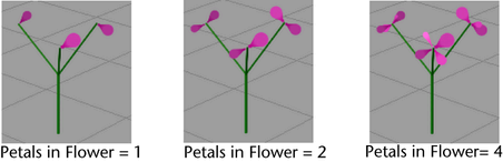
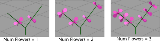
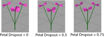
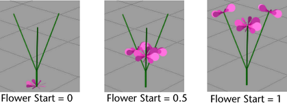
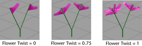
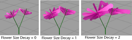
These are the Paint Effects Brush Settings in the Tubes > Growth > Flowers section.
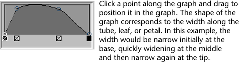
This allows you to use a graph to control the width from base to tip of petals, rather than using a simple linear interpolation between two values. When combined with the Brush Type you can define shapes like spheres, as well as control the profile of a petal. Width Scale is applied as a scale to the current width and defaults to 1.0 so that previous presets work with it.
Turn this check box on so the broad or flat side of a petal is always oriented towards the camera. Textures are similarly affected so that they always face the camera. For more information, see Forward Twist.
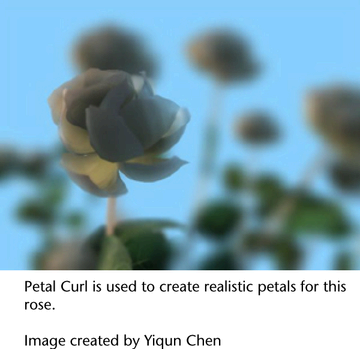
Use the Curl attribute to bend petals in the V direction (along the width). This is perpendicular to the Petal Bend direction. Create and move points along the ramp to define the curl of the petal. The ramp controls the curl from root to tip of the petal. The left side of the ramp is the base of the petal and the right is the tip. Controlling the curl from base to tip can help define the natural shape of petals, as well as prevent interpenetration within a cluster. The mid line value on the ramp (0.5) represents zero curvature. Many petal shapes have curvature that is constantly changing. For example, iris petals or mistletoe leaves can be simulated by a wavy curl ramp.
This setting is available only when Illuminated is turned on (see Illuminated). The Translucence value controls how much the petals transmit and diffuse light. Light shining on the back of translucent petals can light up the front, although you still may not be able to see through them. To make the petals completely opaque, set this to 0. To allow more light to diffuse through, set the value closer to 1.
This is the specular intensity value exclusively for flowers and it controls the brightness of the shiny highlights on illuminated paint. A value of 0 produces no highlights, while higher values produce brighter highlights. This setting is available only when Illuminated is turned on. See Specular in Illumination.
These attributes define how much random variation Maya applies to flower petal colors when creating new tubes. Low values ensure that all petals are created using colors very close to Petal Color 1 and Petal Color 2. Increasing these values causes more random variation. You can control randomness of the Hue, Saturation, and Value individually.
These are the options in the Behavior section of the Paint Effects Brush Settings window.
These are the Paint Effects Brush Settings in the Tubes > Behavior > Displacement section.
Defines the point along the tubes (from the base) where the displacement takes its full effect. The displacement values ramp to this point. If the value is 0, the displacement starts to take full effect at the base of the tubes. If the value is set to 0.5, then the displacement begins to take full effect halfway along the length of the tube (measured in segments). If the value is 1, the displacement starts to take full effect at the maximum tube length.

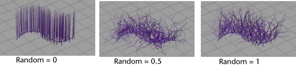
Defines how much random variation to apply to the position of tube segments. The tubes must have a lot of segments for you to see the effect (20 segments in the following example). See Segments.

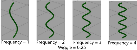
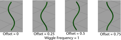
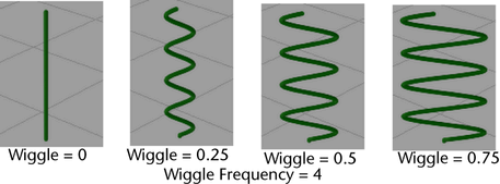
Defines the amount of “wiggle” to apply to tubes. Wiggle is defined by a repeating wave curve. The Wiggle value defines the amplitude of the wave.
The tubes must have a lot of segments for you to see the effect (100 segments in the following example). See Segments.
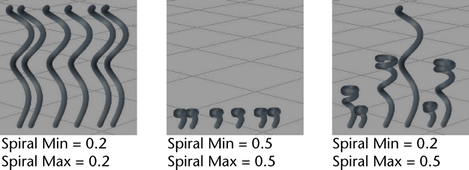
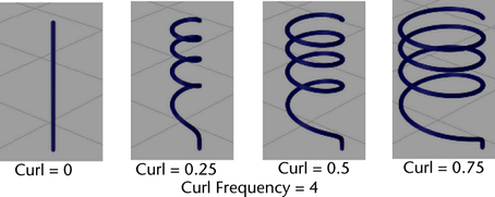
Defines how wide to make the tube curls. The higher the value, the wider the curl. The tubes must have a lot of segments for you to see the effect (200 segments in the following example). See Segments.
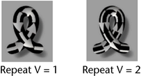
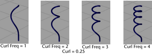
Defines the number of curls applied over the maximum length of the tubes. If you increase the curl frequency, you may also need to increase the number of segments in the tubes to get smooth results. See Segments.
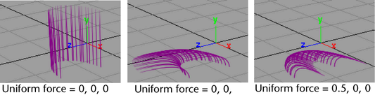
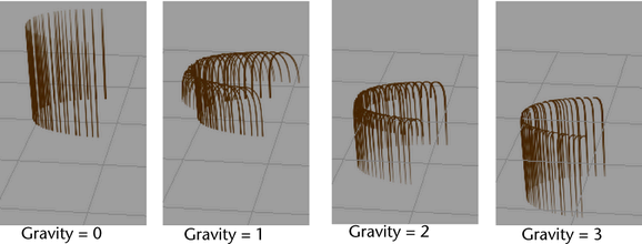
These are the Paint Effects Brush Settings in the Tubes > Behavior > Forces section.
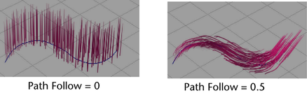
Defines the magnitude of the force that attempts to make tubes grow in the same direction as their corresponding points on the stroke path. If the value is 0, no force is applied to the tubes. As the value increases, the tubes follow the path more closely. A positive value follows the stroke path (like combing the tubes in the direction of the stroke path) while a negative value follows the reverse stroke path (like combing the tubes against the direction of the stroke path).
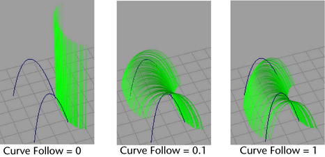
You can make tubes follow control curves that are associated with strokes. For details, see Modify tube behavior using control curves. The Curve Follow setting defines the magnitude of the force that tries to make tubes grow in the same direction as the associated control curves. A positive value attracts tubes while a negative value repels them.
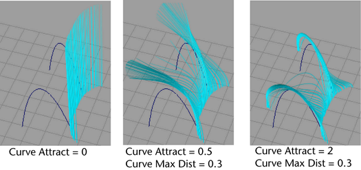
You can make tubes attract to control curves that are associated with strokes. For details, see Modify tube behavior using control curves. The Curve Attract setting defines the magnitude of the force that attracts tubes to the associated control curves. A positive value attracts tubes, while a negative value repels them.
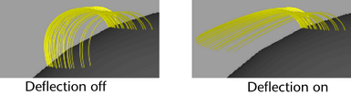
Turn on Deflection to apply a force that stops tubes from passing through the surface or plane they are growing from (for example, when gravity pulls branches down). The force pushes upwards and is stronger closer to the surface or plane.
These settings are available only if Deflection is turned on. They define the range over which the deflection force is applied. Deflection Min is the closest distance (in world units) that the tube can get to the ground before the force becomes effectively infinite. Deflection Max is the distance from the ground where approaching tubes are first influenced by deflection.
These are the Paint Effects Brush Settings in the Tubes > Behavior > Turbulence section.
Turbulence Type
Defines which type of turbulence is created, and how it is applied to the tubes. You can select from the following types:
Defines the mathematical method used to smooth the values (and therefore the motion) in the turbulence calculations. Select from Linear, Smooth over Time, or Smooth over Time and Space.
For a more realistic effect this should typically be set to Smooth over Time and Space. If the highest speed is more desirable than motion quality, select either Smooth over Time or Linear.
These are the Paint Effects Brush Settings in the Length Mappings section.
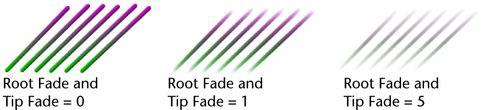
Affects how much of the transparency range (between Transparency1 and Transparency2) is used. If this is set to Length, then every tube uses the whole range. If this is set to maxLength, then only the longest tubes uses the whole range. Shorter tubes start at Transparency 1, but end before they make it to Transparency 2.
Affects how much of the color range (between Incandescence 1 and Incandescence 2) is used. If this is set to Length, then every tube uses the whole range. If this is set to maxLength, then only the longest tubes use the whole range. Shorter tubes start at Incandescence 1, but end before they make it to Incandescence 2.
Affects how much of the width range (between Tube Width1 and Tube Width2) is used. If this is set to Length, then every tube uses the whole range. If this is set to maxLength, then only the longest tubes uses the whole range. Shorter tubes start at Tube Width1, but end before they make it to Tube Width2.
These are the Paint Effects Brush Settings in the User MEL Scripts section. For more information, see Use MEL scripts to apply custom effects.
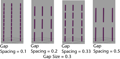
These are the options in the Gap section of the Paint Effects Brush Settings window.
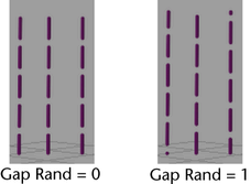
Randomizes the positions of the gaps for each tube. If Gap Rand is 0, all the gaps occur at the same positions for each tube. As this number increases, the spacing becomes more random between tubes.
Gap Rand also randomizes the position of textures applied to tubes, leaves, or flowers, even if Gap Size is set to 0.
These are the options in the Flow Animation section of the Paint Effects Brush Settings window.
Defines the speed (in cycles per second) and direction that gaps, twists, and textures move (or flow) along animated tubes. Positive numbers make them flow from base to tip. Negative numbers make them grow and flow from tip to base.
For example, if the flow speed is two, the gap, twist, or texture pattern cycles (flows back to the starting pattern) twice in one second. So if your units are defined to be 24 frames per second, the pattern made by the gap, twist, or texture pattern will be identical on the 12th frame and the 24th frame.
If you turn on the Time Clip or Stroke Time options, it also defines the speed that tubes grow.
This moves the texture with flow as defined by Flow Speed. In general this is best turned off for growth animations (growth with time clipping) because the textures will not move during the plant growth. But this is useful when you want a texture, particularly a displacement, to flow down the tubes. This is on by default.
Turn on Time Clip so that animated tubes first appear and begin to flow at the time set by Start Time (seconds), and die at the time set by End Time (seconds).
If Time Clip is on, but Stroke Time isn’t, tubes along the stroke path are already planted, which means the tube growth is uniform.
If Time Clip is off, the tubes display at the end of their lifespan along the stroke, the growth simulation having completed. In this case, only gap, twist, or texture flow are animated.
This option has no effect unless Time Clip is on. Start Time (seconds) defines the time when tubes first appear (or are “born”).
If you know what frame you want tubes to appear on, divide this frame number by the frames per second defined by your Time unit to determine what value to enter in the Start Time (seconds) box. For example, if you want your tubes to appear on frame 60 and your Time unit is set to NTSC (30 fps), divide 60 frames by 30 frames per second, for a Start Time (seconds) of 2 seconds.
You can perform this calculation by creating an expression in the field. Type an equals sign (=) followed by the calculation. In the previous example, you would type:
This option has no effect unless Time Clip is on. End Time defines the time when tubes “die.” If you think of a tube as a particle emitter that emits tube segments, the End Time is the point in time when the emitted segments die, or disappear. If the growth simulation is not yet complete, segments will continue to be emitted after the End Time until they reach their lifespan.
If you are animating growth, set this value to occur at the same frame as your end frame or later. With growth, you typically do not want tubes to die before the animation is complete.
To create “bursting” effects, use values that occur at frames before the end frame.
If you know what frame you want tubes to begin to die on, divide this frame number by the frames per second defined by your Time unit to determine what value to enter in the End Time box. For example, if you want your tubes to begin to die on frame 120 and your Time unit is set to NTSC (30 fps), divide 120 frames by 30 frames per second, for an End Time of 4 seconds.
You can perform this calculation by creating an expression in the field. Type an equals sign (=) followed by the calculation. In the previous example, you would type:
Use this option to keyframe time. For example, if you are animating the growth of a tree, you can make the tree remain a sapling for the first 100 frames of the animation, then have the tree grow from a sapling to a full grown tree in the next 100 frames.
To keyframe time, first right-click in the Time box and select Break Connection. Set keys at the frames you want to control growth (go to the frame, right-click in the Time box and select Set Key). Open the Graph Editor ( Window > Animation Editors > Graph Editor) and edit the animation curve to set the desired values. For details, see the Animation guide.