Show in Contents

Add to Favorites

Home: Autodesk Maya Online Help

Adding polygons to a mesh

Lesson 1: Modeling a polygonal mesh

Terminating edge loops

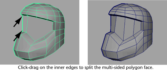
Splitting polygon faces
Earlier
in the lesson you split the helmet mesh by inserting edge loops
across the mesh. You can split localized areas of a mesh using the Split
Polygon Tool. When using the tool you draw a line across
the faces to indicate the location for the split. You'll begin by
vertically splitting the face shield.
To split the face shield vertically
- Select
Edit Mesh > Split Polygon Tool >
 .
.
The Split
Polygon Tool settings editor appears.
- Set the following options:
- Split only from edges:
On
- Use snapping points
along the edge: On
- Snapping tolerance:
100
These settings let you
begin and end your split at a location that corresponds exactly
with an edge and lets you snap to the midpoint and ends of the edge
you select. (The number of points setting of 1 ensures this). These
settings will help to ensure that the faces you split align exactly and
that the four-sided topology of the mesh is maintained.
- Tumble the camera in the perspective
view so you can view both the upper inner edges of the face shield
as well as the lower inner edges.
- Click-drag the top inner edge of the
face shield to indicate the start of the split (see image below).
Drag the mouse to position the vertex until it stops at the right
side of the edge.
- Click-drag on the lower inner edge of
the helmet mesh to indicate the end of the split (see image). Drag
the mouse to the right until the vertex stops at the right side
of the edge.
- Press the y key to split the face.
- Press the g key to select the Split
Polygon Tool again, and then continue to split the face
shield vertically at the other locations specified in the image
below. Remember to press the y key after each split and then the
g key to select the tool again.
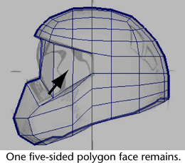
When you are finished
the n-gon for the face shield will be split into four or five new
polygons (depending on how you've constructed your mesh).
One polygon on the side
of the face shield will still be five-sided. To correct this, you'll
also split the face shield horizontally. Splitting the face shield
horizontally will also let you modify its shape afterwards.
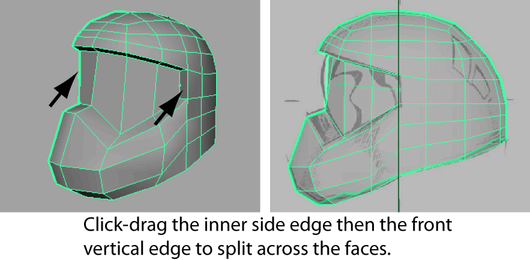
To split the face shield horizontally
- In the perspective view, with the Split
Polygon Tool still active, click-drag the inner side
edge (see image) to indicate the start location for the horizontal
split.
- In the side view, click-drag the front
vertical border edge of the face shield (this border edge lies on
the axis of symmetry) and release the mouse button at the mid-point
along the edge where the vertex naturally snaps (as if a magnet
were attracting it towards that location).
- Press the y key to split the faces.
NoteWhen you split across
multiple faces at the same time you only need to click an edge to
indicate the start point for the split and on a second edge to indicate
the end point. The Split Polygon Tool automatically
splits the edges in between.
- Press the q key to quit the Split
Polygon Tool.
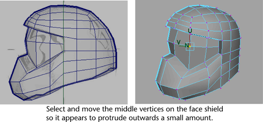
In the next steps you'll
reposition some of the vertices along the horizontal split to make
the face shield protrude outwards a small amount.
To adjust the shape of the face shield
- In the side view, select the middle
two vertices at the front of the face shield and use the Move
Tool to move the vertices outwards (+Z) a small amount
(see image).
- In the perspective view, select the
remaining middle vertices on the face shield one at a time and reposition
them outwards a small distance using the Move Tool with
the Move Setting option set to Normal.
TipTumble the perspective
view so you can see the relationship between the vertices as you
move them outwards.
- Reset the Move Tool's Move
Settings to World before
continuing to the next steps.
To create the diagonal
grill vents on the lower front of the helmet you’ll insert edges
on the face, reposition some of the vertices, and then extrude some
of the faces.
To insert multiple edges for the diagonal
grill vents
- Select
Edit Mesh > Insert Edge Loop Tool > .
- In the Insert Edge Loop Tool
Options window, set the following:
- Multiple Edge Loops:
On
- Number of edge loops:
4
- Auto Complete:
Off
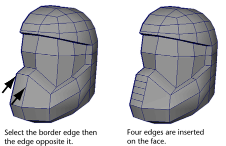
These settings let you
insert four evenly spaced edges on the face where you want the grill
vents to appear.
- In the perspective view, click the border
edge of the face where the grill vents will appear and then click
the edge directly opposite that border edge (see image).
- Press the y key to complete the edge
loop insertion
- Click off the mesh to deselect the edges.
- Press the q key to exit the tool and
return to selection mode.
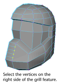
To make the grill vents
appear diagonally you’ll select the vertices on the right side and
then slide them downwards using the Move Tool.
To move vertices along an edge using
the Move Tool
- Right-click the helmet mesh and change
the selection mode to Vertex.
- Select the vertices on the right side
of the grill feature (see image below).
- Double-click the Move
Tool icon to display the Move Tool’s
settings editor.
- In the Move Tools’
settings editor, click the Set to Edge button.
The vertices appear unselected
temporarily. The Move Tool expects you to select
an edge it will reference for the axis of movement.
- Click an edge that is on the same line
of the edges as the vertices you selected.
The Move
Tool manipulator appears and is aligned to the edge you selected.
The vertices appear selected again indicating that the Move
Tool is now set to move those vertices along the axis
defined by the edge you selected.
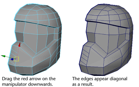
- Drag the red arrow on the Move manipulator
downwards to move the vertices so that the shape of the faces for
the grill are more diagonal (see image).
NoteMake sure you do
not move the vertices so that the lowest vertex touches the corner
vertices or you’ll create an edge that has zero length.
- Click off the mesh to deselect the vertices.
- Before proceeding to the next section,
double-click the Move Tool and reset the tool
settings by clicking the Reset Tool button.
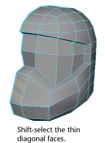
To make the grill vents
three-dimensional, you’ll extrude some of the thin diagonal faces
inwards.
To extrude the faces for the grill feature
- Right-click the helmet mesh and change
the selection mode to Face.
- Beginning at the bottom of the grill
feature, shift-select the two diagonal faces as indicated in the
image below.
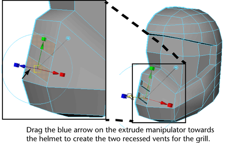
- Select
Edit Mesh > Extrude.
The Extrude manipulator
appears.
- Drag the blue arrow on the Extrude manipulator
towards the helmet a short distance to create the two recessed vents
for the grill.
- Press the q key to quit the Extrude feature.
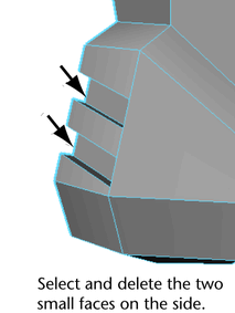
- Shift-select the two side faces on the
grill vents that lie on the axis of symmetry and delete them (see
image below). These faces will not be required when you create the
opposite half of the helmet.
- Save your work before proceeding to the
next section.