Show in Contents

Add to Favorites

Home: Autodesk Maya Online Help

Extruding polygon components

Lesson 1: Modeling a polygonal mesh

Adding polygons to a mesh

Bridging between edges
Next
you’ll connect the lower front region to the helmet mesh. You can
create meshes that bridge between one or more border edges of a
mesh using the Bridge feature (
Edit Mesh > Bridge).
When using the bridge
feature you must ensure that:
- the edges to be bridged are in the same
polygon mesh. That is, you must combine the two meshes into one
using the Combine feature, before you perform
the bridge.
- you select an equal number of border
edges on either side of the region to be bridged.
To combine the two meshes into one
- In the perspective view, right-click
the mesh and select Object Mode from the marking
menu that appears.
- Select the helmet mesh, and then shift-select
the lower front mesh, so both meshes are selected.
- Select
Mesh > Combine.
The
two meshes are combined into one. When you select either object now,
the other is also selected because they are in the same mesh.
The edge of the mesh
on the lower front region of the helmet is comprised of five edges.
The corresponding region on the side region of the helmet only has
three. You can increase the number of edges on the lower side region
by inserting two edge loops across the mesh. Inserting two edge
loops in this region of the mesh also divides the large faces so
they better match the size of the other faces on the rest of the
mesh.
To insert edge loops on the side region
of the helmet
- Select
Edit Mesh > Insert Edge Loop Tool >
 .
.
The Insert Edge Loop Tool settings
editor appears.
- In the tool settings editor, set the
following options:
- Maintain Position: Relative
distance from edge
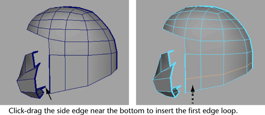
- In the perspective view, click-drag the
edge on the side region of the helmet near the bottom of the edge
as indicated in the image below. Without releasing the mouse button,
drag the mouse upwards about one third of the distance along the
edge and then release the mouse button to insert the edge loop.
NoteClick-dragging an
edge when using the Relative option inserts an edge
loop that closely matches the existing edge layout on the mesh.
That is, the lower region of the mesh is much wider near the front
than at the rear. The Relative setting
adjusts the position of the edge loop locator based on this topology
so is ideal in these situations. When you click-drag using the Relative option,
remember to click near the edge whose layout you want the edge loop
to match.
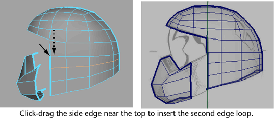
- With the Insert Edge Loop Tool still
active, click-drag the side region of the helmet near the top of
the same edge and insert a second edge loop about two thirds of
the distance along the edge.
- Press the q key to return to selection
mode, and click anywhere off the mesh to unselect the edges.
Now that you’ve inserted
the necessary edges, you can proceed with creating the bridge.
To bridge between the lower front and
side region of the helmet
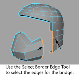
- Choose
Select > Select Border Edge Tool and
then click the border edges on both the lower front as well as the
side region of the mesh where you want the bridging mesh to be constructed.
(You should have five edges selected on either side).
TipWhen you select border
edges using the Select Border Edge Tool you can
click on the first and last edge in a series on one side of the
bridge and the tool will select the edges in between.
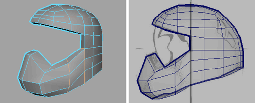
- Select
Edit Mesh > Bridge > .
- In the Bridge Options window,
set the Divisions to 0, then click
the Bridge button to create the
bridge.
- Press the q key to return to select mode,
and click anywhere off the mesh to unselect the edges.
NoteIf your bridge appears
to twist or cross over itself it indicates that the two meshes have
their surface normals mismatched. In this particular case it likely
indicates that you did not create the original profile shape for
the lower front by placing the six vertices in a counter-clockwise
direction.
If this occurs you must
undo your steps to the point immediately before you combined the
two meshes and then reverse the surface normals on only the lower
front section by selecting it and then selecting
Normals > Reverse.
You can then redo the instructions in this section as required.