Show in Contents

Add to Favorites

Home: Autodesk Maya Online Help

Drawing a polygon

Lesson 1: Modeling a polygonal mesh

Bridging between edges

Extruding polygon components
You
can create new polygon components from existing ones using the Extrude feature
(
Edit Mesh > Extrude).
When you extrude a polygon component (for example, a face, edge,
or vertex), you create additional polygon components from the ones
you selected. Using the Extrude feature
you will:
- Create the lower front region of the
helmet by extruding the polygon face you created in the last section
of the lesson.
- Extrude edges
around the face shield and along the lower bottom edge.
To extrude the polygon face for the lower
front region
- Enlarge the scene view to a single perspective
view.
- With the polygon face still selected,
choose
Edit Mesh > Extrude.
The extrude manipulator
appears on the selected face.
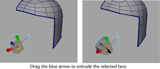
- In the perspective view, drag the blue
arrow on the manipulator to extrude a section of mesh out from the
face (positive X) a distance of approximately one half a grid unit
(see image).
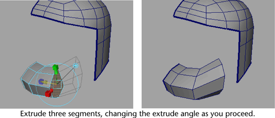
- Press the g key to extrude again.
- Click the large circle that surrounds
the manipulator to display the rotate manipulators and then drag
the green circular manipulator to rotate the angle of the extrusion
to match the angle in the reference sketch (see image) and then
drag the arrow manipulator a second time to extrude a second section
of mesh.
TipAs you change the
angle of rotation and extrude the mesh you can also momentarily
switch between the move or scale manipulators to fine tune the position
and scale of each section as you extrude it.
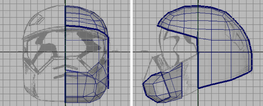
- Press the g key once again and create
a third extruded region using the manipulator to move, rotate, or
scale the extruded segment of the mesh so you position it correctly
when compared to the reference sketch (see image). You may also
want to view the extrusion from either the top or front view to
ensure your extrusion doesn’t extend outwards more than the side
region.
- Save your work.
To delete unwanted faces on the extruded
mesh
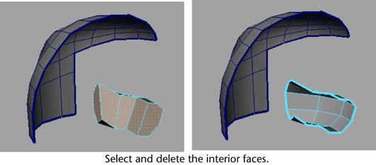
- Tumble the perspective view until you
can view the inside of the lower front region (see image below).
- Select the faces that appear on the inside
of the mesh you just extruded, including the faces on either end
of the extrusion.
These faces were required
for creating the extruded portions of the lower region but are not
needed beyond this point.
- Press the Delete key to delete the selected
faces.
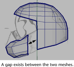
When you are finished,
a gap will exist between the last extruded segment of the lower
region and the helmet mesh.
You’ll combine these
separate meshes together and then create a mesh that bridges between
them in the next section of the lesson. To prepare for the bridge,
you need to extrude more edges on the helmet mesh so that the number
of edges match when you create the bridge.
To extrude the bottom edges of the helmet
mesh
- In the perspective view, select the lower
edges of the helmet mesh using
Select > Select Border Edge Tool.
- Select
Edit Mesh > Extrude,
then drag the blue arrow manipulator in a direction towards the
inside of the helmet to create a row of edges that are perpendicular
to the selected bottom edges. Extrude these edges a distance that
is approximately one grid unit in depth (see image below).
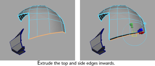
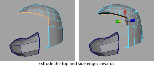
To extrude top and side edges for the
face shield
- In the perspective view, select the upper
and side edges on the helmet mesh using
Select > Select Border Edge Tool (see
image below).
- Select
Edit Mesh > Extrude and
then drag the blue arrow on the extrude manipulator in a direction
towards the inside of the helmet to create edges that are perpendicular
to the top and side edges of the face shield. Extrude these edges
a distance that is approximately one grid unit in depth (see image
below).
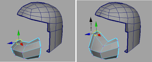
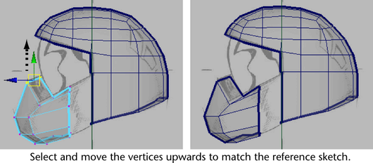
To move vertices on the lower front region
to match the reference sketch
- In the perspective view, right-click
on the helmet and select vertex mode to change the selection type
to vertices.
- Select the four vertices on the lower
front region of the helmet that are near the axis of symmetry (see
image below) and using the Move Tool, move
the selected vertices upwards by dragging the green arrow on the Move
Tool manipulator so that the lower front region of the
helmet matches the reference sketches as they appear in the various
orthographic views.
- Adjust any vertices on the lower region
that may require minor repositioning by selecting and moving them
as necessary.