
The Trash icon lets you remove tool icons or shelves from the shelf area. To get rid of an unwanted item, drag it into the trash while holding down the middle mouse button.
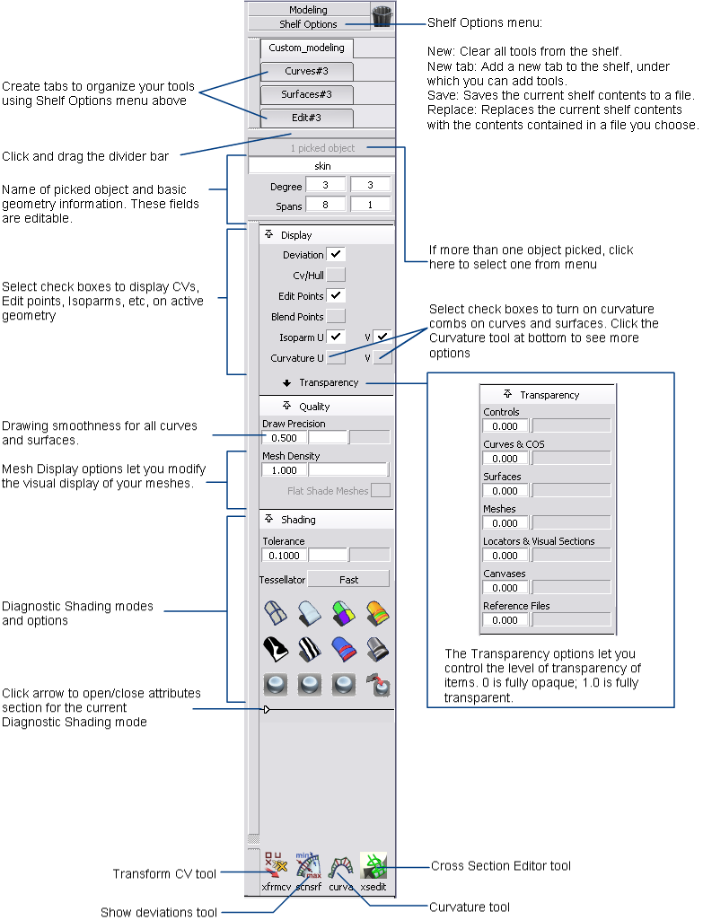
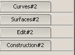
The shelf area contains shelves, which are sets of tools you can customize to help with your workflow. You can change the contents and number of shelf sets in this area, and compress them or expand them by clicking the tabs.
This area also lets you have more window real estate by offering a compact alternative to the main shelf window. For example, you can put all the symmetry tools in the shelf set area and then close the main shelf and palette windows for a larger view of your model.
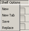
Click the Shelf Options tab for a drop-down menu that lets you add, save, clear, and replace shelf sets in the shelf area.
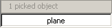
The Pick list isolates a single curve or surface from a collection of curves and surfaces. The white text field displays the name of the picked component.
You can pick more than one object in Alias. The gray text box tallies all picked (and active) components in the modeling space. To view a drop-down list of all selections, and to switch between components, click and hold on the gray text box.
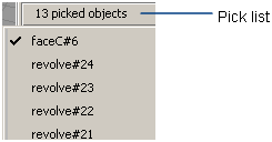
As you move the mouse pointer over an item, the object is highlighted in the view windows. Release the mouse button over an object to pick only that one.
To rename a picked object, type the new name into the white text field.
The rebuild tool works with only one curve or surface at a time. Use the Pick list or the Pick > Component tool to choose one curve or surface from a collection of curves and surfaces.
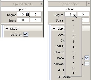
The Rebuild options let you quickly change the degree (from 1 to 9) and the number of spans of the picked curve or surface through one of the following methods:
If the degree or spans of a curve or a surface are modified, this tool maintains the original distribution of spans while creating additional ones as needed, and does not change the parameterization of the geometry.
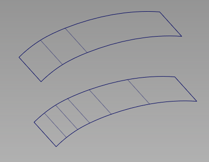
Surface with 3 spans in the U direction (top) is rebuilt with 6 spans in U (bottom).
For a surface, changing the degree or number of spans in one direction (U or V) does not affect edges running in the other direction.
When a degree or span value is modified:
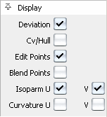
For a better view of your design, the Display options let you display or hide the following items on the picked geometry:
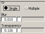
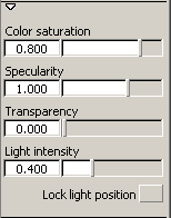
This set of options lets you control the level of transparency of geometry and other items such as locators and canvases.
Transparency is achieved by blending the object color into the background color.
These sliders are also available from WindowDisplay > Transparency ❒.
❒.
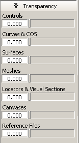
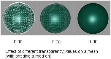
A value of 0.0 means the item is completely opaque. A value of 1.0 means the item is completely transparent and invisible.
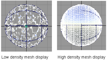
This set of options lets you adjust the display of your curves, surfaces, and meshes.
However, it only affects the visual display of the geometry, not the geometry itself.
For more information on meshes, see Meshes.
The icons under Shading shade your geometry so you can view and evaluate your surfaces. The various shading modes provide different diagnostic information about surfaces.
Some tools in diagnostic shading, such as Horizontal/Vertical, simulate light reflecting against the surface of your model. Reflecting light on a surface is a good way to check for any bumps, dents, or other irregularities. Reflections also point out any surfaces that do not meet smoothly.
Curvature Evaluation tools color-code the curvature of your surfaces. Color-coding the curvature is useful when, for example, your model will eventually be made in a material that only bends a certain amount before breaking.
Surface Evaluation contains a draft angle map. This diagnostic tool is useful for products produced through injection molding. If the sides of a mold are too steep, an object cannot part with its mold. Draft Angle evaluation shows which parts of an object are in-draft and which are out-of-draft.
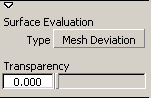
Finally, Surface Evaluation includes a way to map mesh deviations. If you have scanned an object, and are trying to match the scan data with your model, mesh deviation lets you know where the two surfaces are not the same.
You can continue to adjust CVs while diagnostic shading is on.
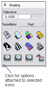
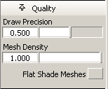
This slider controls how accurately surfaces are triangulated when the Tessellator is set to Fast. The slider range is 0.01 to 1.
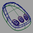
The picture shows a surface with the tolerance slider set to 1. The portions where the shading does not entirely meet the wireframe show the triangulation has been quick but not perfectly accurate. This effect is called “nickeling”. If the slider is set to 0.01, the surfaces of the model become completely shaded because the triangulation is more accurate, however, the process takes longer. Choosing a tolerance value means balancing time versus appearance.
When the tessellator is set to Fast, models are triangulated more quickly and less accurately. When the tessellator is set to Accurate, models are triangulated more accurately and slowly.
When set to Accurate, a check box is added for Limit Edge Length. If this box is checked, a slider is added for Max. Edge Length. Max. Edge Length is the maximum length (in current units) of a triangle created by tessellation.
The wireframe model appears with no shading. This icon clears the wire model of its current shading. No options are available with this shading mode.

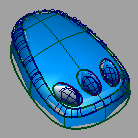
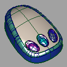
The Multi Color icon shades all the picked surfaces with a single color that you can choose. Use this shading mode to see how your model looks as a finished product, and detect any bumps, dents or other surface irregularities.
You can control the shading qualities with the Light options.
By default, Diagnostic Shading uses a point light located at the eye position of the camera. You cannot see or pick this light as an object, but you can change its parameters through the following options.
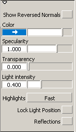
Normally the light source for the shading comes from the camera (like a headlight). Turn on this option to lock the light source in its current position.
Normally, the highlights move over the model as you tumble around it. Turn on this option to lock the light source in its current position. The highlights remain stationary as you tumble.
Choose a reflection map by clicking Scene for a drop-down menu.
Sky environments images copyright © 2004 Dosch Design GmbH. For more textures, 3D models and HDRIs, please visit http://www.doschdesign.com.

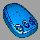
Random color mode shades the surfaces with random colors. As a result, adjacent surfaces show up in different colors, making it easier to see the patch structure, and how the patches align with one another.
You can control the qualities of the shading with the Random Color options. These options appear in the Modeling panel when you click the Random Color icon. For the most part, they are the same as the options documented for the Multi Color icon. However, instead of a Color slider, there is a Color saturation slider.

This mode includes nine ways to view curvature. The tools color-code the curvature of your surfaces. Color-coding curvature is useful for evaluating the curvature of your model. You can see where the curvature changes either abruptly or subtly. You can also find potential flaws.
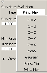
The Curvature Evaluation Type settings listed in the image calculate the curvature of surfaces on each point. This calculation measures the diameter of a circle that touches the surface at each point. Points that have a circle with the same diameter are displayed with the same color. Each point can have several circles. The Curvature Evaluation Type settings specify which circles are used for the calculation.
The Crv U and Crv V settings orient the circle of each point in the U/V direction.
The Crv X, Crv Y, and Crv Z settings orient the circle of each point in the X, Y, and Z direction.
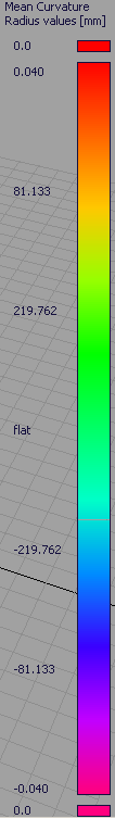
The Gaussian setting, as demonstrated in the image, multiplies the value of the smallest circle and the value of the largest circle. The Mean setting takes an average of the two principal curvatures and displays average curvature.
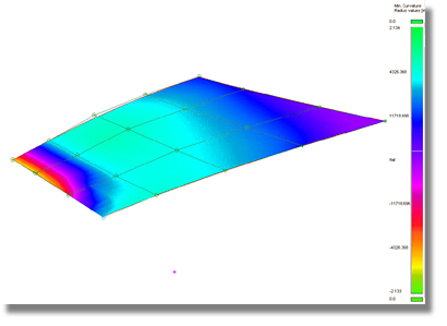
Areas where the surface has inflections or holes can be easily detected by examining the accompanying color bar for negative radius values. The Radius Ramp button in the Surface Evaluation options controls the color bar.
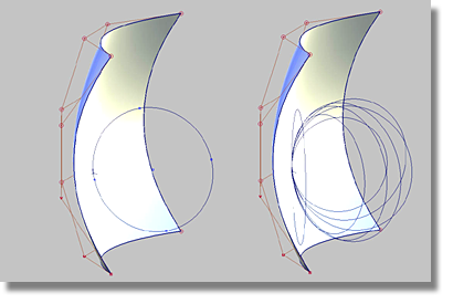
Both the Princ. Min and Princ. Max settings measure radii size. To meet manufacturing requirements, it is necessary to evaluate a surface model for the maximum or minimum radii size. All radii that fall above or below a defined value must be detected. A slider can be used to enter the value.
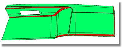
In the image below, the surfaces, or areas of surfaces that fall below the defined radius limit are highlighted in red through the Princ. Max setting.
The following list summarizes the Curvature Evaluation types:
Other Curvature Evaluation Options
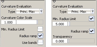
One color indicates surface regions having a radius less than the Min. Radius Limit value, and a different color indicates surface regions having a radius greater than the Min. Radius Limit value.
As you adjust the Min. Radius Limit slider, the radius ramp and the curvature shading on the model update interactively.
This option is only available for the Princ. Max evaluation type.
One color indicates surface regions having a radius larger than the Max. Radius Limit value, and a different color indicates surface regions having a radius less than the Max. Radius Limit value.
As you adjust the Max. Radius Limit slider, the radius ramp and the curvature shading on the model update interactively.
This option is only available for the Princ. Min evaluation type.

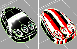
Highlighting helps you find surface flaws. A common use for highlighting is to identify adjacent surfaces with mismatched tangents—in other words, surfaces that do not meet smoothly. You can also use Surface continuity for this purpose, but highlighting gives you a clearer view of the surfaces.
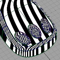
Through a light source manipulator, this mode lets you sweep a single beam across a surface. You can see where the reflected light does not move smoothly. A jump in the reflection indicates flaws in either the surface or its boundary with a second surface.
Multiple beams colored red, black, and white can also be used.
To control the reflection through the Iso Angle options in the Modeling panel, the reflection must be turned on. Select the object and click the Evaluate > IsoAngle tool in the Evaluate palette.

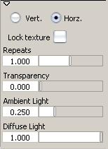
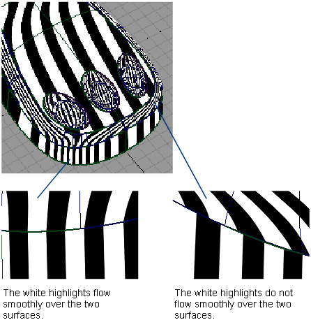
This mode shows horizontal or vertical highlights on the surface.
Highlighting helps you find surface flaws. A common use for highlighting is to identify adjacent surfaces with mismatched tangents—in other words, surfaces that do not meet smoothly. You can also use Surface continuity for this purpose, but highlighting gives you a clearer view of the surfaces.
This mode lets you sweep a multiple black and white highlights across a surface. You can see where the highlights do not move smoothly. A jump in the highlight flow indicates flaws in either the surface or its boundary with a second surface.

This mode includes three ways to evaluate different aspects of your surfaces: Draft Angle, Deviation Map, and Contact Analysis.
Some manufacturing procedures, like injection molding, require objects to be designed with the molding process in mind. Molding imposes restrictions on the shape of an object. If the sides of the mold are too steep, the object cannot leave the mold.
The mold parts are pulled away from the object in a straight line known as the pull vector. The draft angle is the minimum allowable angle between the sides of the mold and the pull vector. If part of a surface has an angle less than the draft angle, the object cannot part with its mold, and the angle is said to be out-of-draft. The opposite of out-of-draft is called in-draft.
The Draft Angle evaluation mode colors in-draft parts of the surface blue and out-of-draft parts of the surface red. You can also display a tolerance region in pink.
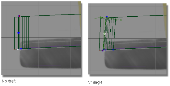
In the pictures above, the draft surface is angled in to the pull direction by 5 degrees. This angle allows the model to be withdrawn from the injection mold.
The Draft Angle Type works best when each normal of the selected surface set points in the same direction, either inwards, or outwards.
To gain more functionality, use the Draft Angle Type setting in the Control Panel in conjunction with the options from the Evaluate > Parting Line tool.
These shading options display which parts of a surface are in-draft and out-of-draft for a specified pull vector and draft angle. These options appear when you select Draft Angle through the drop-down menu for the Type button.
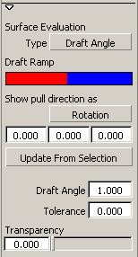
Rotation – Displays values for the X, Y, and Z rotation of a vector that defines the pull direction.
Vector – Displays values for the X, Y, and Z coordinates of a vector that defines the pull direction.
In the three entry fields following Show pull direction as, enter 3D coordinates to define a direction in which the object would be removed from its mold. For example, if you want the pull vector to run along the Z axis, enter 0, 0, 1.
This entry field defines the boundary between in-draft (blue) and out-of-draft (red).
Enter the draft angle. If the angle between a surface point and the pull vector is less than this value, the surface point is out-of-draft, and is colored red.
If the angle between a surface point and the pull vector is more than this value, the surface point is in-draft, and is colored blue.
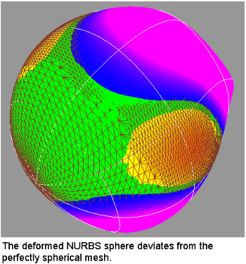
If you have scanned an object, and are trying to match the scan data with your NURBS surfaces, the Deviation Map mode lets you know where the two objects deviate. It calculates the distance between a set of meshes and a set of NURBS surfaces, and displays it as a color-coded map, for a quick assessment of the severity of the gap.
Deviation Map can also show the deviation between two sets of surfaces, or two sets of meshes.
This mode acts as a toggle. It only displays the shading once it has been calculated once through the use of Evaluate > Deviation Map .
.
See also Visualize the deviation between mesh-surface, surface-surface or mesh-mesh
This type of surface evaluation provides you with an ability to analyze the safety of a model. It is especially useful with car interior surface design work.
Equally capable of working with meshes and NURBS surfaces, this shading mode enables you to examine a collection of surfaces for potential impact points with a head (represented by a sphere).
The tool internally creates a sphere, to judge where the head could contact the surface model. For example, some spaces, like between the steering wheel and the dash board, are too small for the head to fit into. Only the areas where a head can actually fit in the case of an accident are examined for sharpness and safety issues.
Before analyzing the model, ensure that normals are unified. If they point in different directions, results will be unreliable.
This mode acts as a toggle. It only displays the shading once it has been calculated once through the use of Evaluate > Contact Analysis .
.
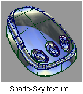
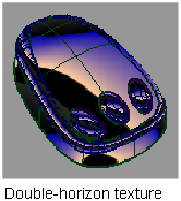
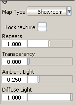
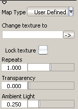
This mode shows a texture map with a Showroom, Photo-Horizon, Diffuse, Shade-Sky, Double-horizon, or User Defined image, depending on the setting of the Map Type option.
Highlighting helps you find surface flaws. A common use for highlighting is to identify adjacent surfaces with mismatched tangents—in other words, surfaces that do not meet smoothly. You can also use Surface continuity for this purpose, but highlighting gives you a clearer view of the surfaces.
This mode lets you sweep a texture reflection across a surface. You can see where the reflection does not move smoothly. A jump in the reflection indicates flaws in either the surface or its boundary with a second surface.

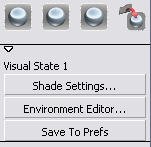
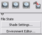
Click one of the three Visual State buttons to turn on hardware shading and shade the model using the environment and shading settings associated with the button.
You can change the settings associated with each of these buttons by clicking the button preset you want to change and using the Visual State options. The settings for the three Visual State buttons are stored with your user preferences.

The settings for the last active environment are stored with the File State button when you save your file. The settings are saved with the file, so anyone opening the file can set the environment to your last active environment using this button.
You can change the settings associated with the File State button by clicking the button and using the File State options. Save the file to save the new settings with the button.
Clicking on one of the tools in the bottom row of the Modeling Control Panel opens up an option sub-panel for that tool. These options are described on the following pages.