Controls the direction, shape interpolation and the placement of the shape of the object.
See Change the form of original object in an animation.
Metamorphosing same-topology items
Set key shape lets you transform one object into another by transforming CVs.
There are two types of interpolations that can be created:
The Interpolation options determine the type of shape interpolation that is performed.
Key shape – Creates CV animation that interpolates from the original object to the new shape.
ShapeShifter – Creates a group of clusters and control objects that interpolates from the original object to the new shape.
The Shape Center options determine the placement of the new shape with respect to the current shape of the object.
First CV– The First CV on the new shape (represented as a small square) matches position with the first CV on the original object. The easiest way
to determine which CV is the first one on a object is to pick the object, then use the pick walker ( +
+  ) to walk to the first CV on the object.
Centroid – The volumetric center of the new shape matches position with the volumetric center of the current shape.
Scale Pivot – The scale pivot of the new shape matches position with the scale pivot of the original object.
When ShapeShifter Interpolation is selected, several additional options are displayed in the Set Keyshape Options window.
The Control name options determine how the name of the control object is displayed. The control object is the object which when transformed
using Transform > Move will cause the original object to change shape.
Prompt – A prompt is displayed asking for the name of the control object.
From target – The name of the control object is derived from the name of the target object.
The Control parameter options determine which translation direction of the control object will affect the ShapeShifter interpolation.
Moving the control object in either of the other two axes has no effect on the ShapeShifter interpolation.
X,Y,Z Translate – Moving the control object in the X, Y, or Z direction determines the amount of interpolation applied to the original object.
The Control range settings determine the range of translation of the control object that affects the ShapeShifter interpolation. These settings also control the placement of translation of the control object on the axis.
When checked ON, all CVs are added in the original object as a cluster, whether or not the CV will ever be affected by the ShapeShifter interpolation.
When checked OFF, only the CVs that need to be transformed are added to the clusters, reducing the number of CVs being affected by the cluster. The default setting is OFF.
The location, in world space, of the slider geometry can be set here. This lets you position the object anywhere that is convenient.
The slider position co-ordinates are only used to position the slider bar. The Control Range settings override the slider position co-ordinates in the control parameter axis. For example, with the default settings, the slider bar ignores the X co-ordinate set for the slider position and instead uses the control range values for the X co-ordinates.
Always return the shapeshifter base object to its neutral, undeformed position before creating the next shapeshifter target pose.
You may also re-order the clusters in the cluster editor so that the new shape-shifter clusters appear before any existing clusters on the object.

The system prompts:
Pick the curves or surfaces which are to change shape. Press GO when ready.
Enter a keyframe value(s) for the picked item(s) current shape (last frame set is 0):
 (Windows) or
  (Mac). The system displays the message:
Setting keyframes for 4 CVs of object (curve#2)
You are then prompted to pick the curve or surface to match and set keyframes for these elements.
How to use key shape interpolations
You are then prompted to select another shape and enter a keyframe time at which the original objects should take on this new shape. Selecting new shapes can continue until all modified copies have been selected and keyframe times are set for them.
The key shape animation is created by animating each of the CVs of the original objects. The interpolation between the CVs (the process that transforms one key shape into another) is, by default, a smooth interpolation. You can adjust this interpolation by modifying the tangents of the animation curves of the CVs in the Action Window.
When you complete the key shape animation, you can delete the animation and start again if you are not satisfied with the
results. However, before deleting the animation, you may want to restore the original shape of the transforming object. If
you typed a keyframe time for the original shape, this is easily done by choosing Animation > Show > View Frame and typing the time of that keyframe.
When satisfied with the animation, you can delete the intermediate objects as their shapes are now recorded as keyframes.
You can use any number of interpolation shapes. Each shape must have identical topology. It is recommended that you copy the
original geometry (the geometry shape for the first keyframe), then manipulate the copied geometry into the desired shape
for subsequent keyframes. If you are interpolating curve shapes, you can use Curves > New Curves > New CV Curve or Curves > New Curves > New Edit Point Curve
 and set Knot Spacing to Uniform in the option window to ensure that you create curves with identical topology.
The objects that are used to transform the original object must have the same topology as the original object. Surfaces with same topologies have the same number of CVs in the U and V parametric directions. Curves must have the same number of CVs.
In this example, a sphere is used to create an interpolation animation where the sphere takes on a diamond shape through 10 keyframes, then reverts to its original shape through another 10 keyframes, and back to the diamond in another 10 keyframes.
 and place a sphere in the Left window at -5,0,0.
 and type 4 to scale the sphere to a value of 4 units.
 ❒ and make sure the CVs is toggled ON (indicated by a check mark). Press GO.
 to ensure that no geometry is active, then choose Pick > Point Types > CV
 and using the bounding box technique, select only the first row of CVs along the top of the second sphere.
and use the
and using the bounding box technique, select only the first row of CVs along the top of the second sphere.
and use the  to move these CVs upwards along the Z-axis to elongate the top of the sphere into a pointed shape.
to ensure that no geometry is active. Select the last row of CVs along the bottom of the second sphere.
and use the to move these CVs down the Z-axis to elongate the bottom of the sphere into a pointed shape.
to ensure that no geometry is active. Select the middle row of CVs of the second sphere.
and use the
to move these CVs upwards along the Z-axis to elongate the top of the sphere into a pointed shape.
to ensure that no geometry is active. Select the last row of CVs along the bottom of the second sphere.
and use the to move these CVs down the Z-axis to elongate the bottom of the sphere into a pointed shape.
to ensure that no geometry is active. Select the middle row of CVs of the second sphere.
and use the  to scale these CVs up to create a bulge in the middle section of the shape so that it resembles the diamond shape shown in
the diagram at the right.
to scale these CVs up to create a bulge in the middle section of the shape so that it resembles the diamond shape shown in
the diagram at the right. 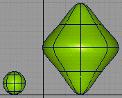
The original sphere defines the start shape and the modified sphere defines the final interpolated shape. Although only two shapes are being used in this example, several interpolated shapes could be used.
to ensure that no geometry is active, then choose Animation > Tools > Set Key Shape . The system prompts:
Pick the curves or surfaces which are to change shape. Press GO when ready.
If you were including other geometry animation, you would continue to select geometry in response to the prompt.
A small GO icon appears in the lower right corner of the active window, and the system continues to prompt:
Pick the curves or surfaces which are to change shape. Press GO when ready.
Enter a key frame value(s) for the picked item(s) current shape (last frame set is 0):
(Windows) or (Mac).
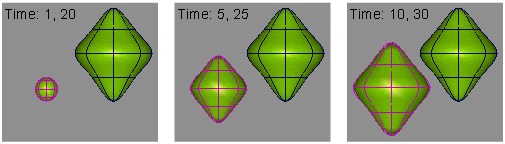
This indicates that the shape of the initial sphere is to be used for keyframes 1 and 20. The system prompts:
Pick the curve or surface to match.
If the surface you select to match does not match the topology of the surface you select to change shape, an error message is displayed and the system prompts:
Pick the curve or surface to match.
If the topology of the selected surfaces match, the system prompts:
Enter a key frame value(s) for this shape (last frame set is 20):
(Windows) or (Mac).
This indicates that the shape of the manipulated sphere is to be used for keyframes 10 and 30.
 to view the interpolation animation.
During playback, the initial sphere shape interpolates into the shape of the manipulated sphere through frames 1 to 10. It then interpolates back to the original shape through frames 10 to 20, then back to the manipulated shape through frames 20 to 30.
How to create ShapeShifter interpolations
With ShapeShifter, an unlimited number of expressions and forms can be combined to transform objects into a variety of shapes, as well as mixing facial expressions together.
ShapeShifter transforms (or “morphs”) one shape into another by transforming CVs using clusters and expressions. This lets you select how much of the interpolation should be applied at any particular time, as well as mix several different target shapes together. Because clusters are used, the underlying geometry can be polygonal or NURBS. Source and target objects can also be hierarchical, as long as the hierarchies match.
ShapeShifter greatly simplifies complex facial animation. For example, given a base (or neutral) face, and other faces that represent a smile and frown, you can create a face which is 75% smiling and 50% frowning and control the timing of the interpolation between the various targets.
The interpolation is done by determining the translation which will make a CV in the source object move to the corresponding CV in the destination object. Therefore the two objects must share the same topology (that is, they must have the same number of CVs in both u and v).
The interaction is simple — for each target, a “control” object is created. The X translation of this object determines the amount of transition from the base to the target object and, of course, can be animated. For example, to have the neutral face ease into a smiling face over two seconds, you simply move the control object to the left of the slider, set a keyframe at 0, then move the control object to the far right and set another keyframe at 60. Set the animation interpolation in the Action Window on the control object’s X_translation channel (or use an expression) and you’re ready to go.
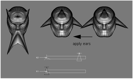
The following example shows how ShapeShifter is used to combine features from two separate head expressions.
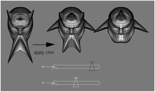
The middle head combines the features from the other two heads. The head on the left has been manipulated to exaggerate the chin and horns of a little devil. The head on the right has a pointier head, as well as some devilishly handsome ears.
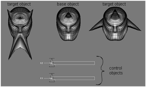
Moving the control object of the top slider causes the middle head to acquire some of the features of the head on the right. Notice how the middle head is also pointier, and has begun to sprout its own pair of ears. The amount of shape-shifting can be controlled by the position of the slider.
As you start to move the control object of the bottom slider, notice how the middle head begins to acquire some of the characteristics of the left head as well as retaining the effects of the right head.
The source and destination objects must share the same topology (they must have the same number of CVs in both U and V). The interpolation is done by determining the translation which makes the CV in the source object move to the corresponding CV in the destination object.
To set the options:
❒, then click ShapeShifter in the Interpolation section of the option box.
A DAG node containing 3 clusters and a DAG node for the control object are created.
If Create control geometry is checked, a triangular object is included in the control object DAG node.
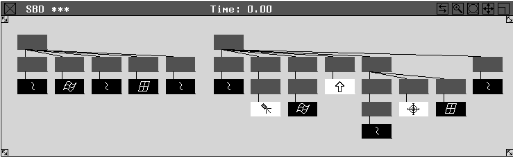
Hierarchical ShapeShifter interpolations
ShapeShifter interpolations can also be created between objects consisting of many grouped geometry nodes.
For grouped objects, the Shape Center is created as follows:
The following is an example of the SBD view with two diverse hierarchies, which can still be used for ShapeShifter interpolations. Geometry nodes are matched up going from left to right through each object.