


Lets you place an object on another object or in space, based on input points (or existing construction planes) on both the source object and the target location.
Transform > Object Placement > Place  enables you to position an object based on input points that describe either a single point, an axis (2 points) or a plane
of reference (3 points or an existing construction plane) on both the source object and the target location.
enables you to position an object based on input points that describe either a single point, an axis (2 points) or a plane
of reference (3 points or an existing construction plane) on both the source object and the target location.
If only one point is selected on both the source and target, the source object is simply translated so the two points coincide. If two points (an axis) are specified on each, the transformation applied to the source object consists of both a translation and a rotation so the two axes match.
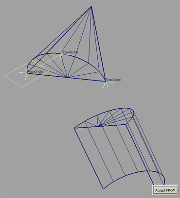
If three points (a plane) are specified, the tool calculates the appropriate transformation and translate/rotate the selected geometry (source object) to the established target position so that the two oriented planes coincide. The source object is placed according to the location and order of the points picked on the target location.
.
After positioning the first point, a point locator is displayed. After positioning the second point, a vector between the two points is displayed. After positioning the third point, a plane is displayed.
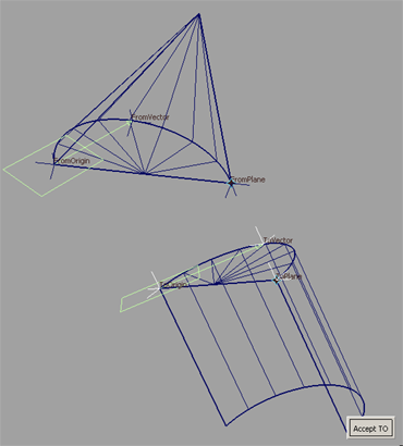
The object is moved and rotated so that the planes defined by the two sets of points you selected in steps 3 and 5 coincide.
The transformation can be undone by choosing Edit > Undo . This causes the geometry to return to its original position, but maintains the point selections on the source and target
locations.
. This causes the geometry to return to its original position, but maintains the point selections on the source and target
locations.
The points are deleted by default. To keep the points around, turn off the Delete points when finished option in the option box prior to exiting the tool.
If the points were not deleted, you have the option of re-entering the Place tool and selecting/modifying the existing points at a later time.
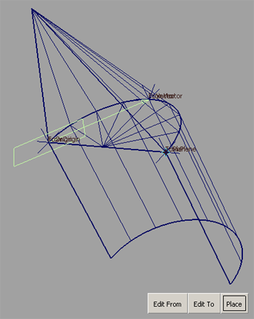
To modify the position of the points (at a later time):
.
The labels on the 3 "from" points (FromOrigin, FromVector, FromPlane) become visible.
The labels on the 3 "to" points (ToOrigin, ToVector, ToPlane) become visible.
The new transformation is calculated and the object is moved and rotated so that the planes defined by the new point locations match.
 to start over and place another object, or choose another continuous tool to exit.
 or
or  snap to help position the points by attaching them to a CV, edit point, or curve. Use
  snap to snap a point to a grid intersection or detach an existing point (created through the use of the tool) from the geometry.