Autodesk® ViewCube® navigation tool and NavBar provide the same viewing functionality found in the View Panel.
Overview of ViewCube and NavBar
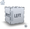
The ViewCube tool is a persistent, clickable and draggable interface that you use to switch between standard and isometric views of your model. By default, it displays in the top right corner of the perspective window in an inactive state. While the ViewCube tool is inactive, it provides visual feedback about the current viewpoint as view changes occur. When you position the cursor over the ViewCube tool, the tool becomes active; you can switch to one of the available preset views, roll the current view, or change to the Home view of the model.
The NavBar is a tool panel associated with Autodesk® ViewCube®. It provides supplemental navigation functions that correspond with functionality on the View Panel.
Use the ViewCube and NavBar view control
You can use the new ViewCube tool and NavBar, or the View Panel to control your view, or you can choose to use neither.
To select ViewCube and NavBar as the view control
To display ViewCube and NavBar
 + .
+ . (also + Command
 on the Mac).
Reorient the view with ViewCube
Use ViewCube to reorient the current view of a model. You can reorient the view with the ViewCube tool by clicking predefined areas to set a preset view as current, click and drag to freely change the view angle of the model, and define and restore the Home view.
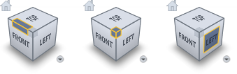
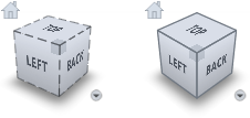
The ViewCube tool provides twenty-six defined areas you can click to change the current view of a model. The twenty-six defined areas are categorized into three groups: edge, corner, and face. Of the twenty-six defined areas, six of the areas represent standard orthogonal views of a model: top, bottom, front, back, left, and right. Orthogonal views are set by clicking one of the faces on the ViewCube tool.
Use the other twenty defined areas to access angled views of a model. Clicking one of the corners on the ViewCube tool reorients the current view of the model to a three-quarter view, based on a viewpoint defined by three sides of the model. Clicking one of the edges reorients the view of the model to a half view based on two sides of the model.
To reorient the current view to a preset orientation
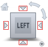
When you view a model from one of the face views, two roll arrow buttons display near the ViewCube tool. Use the roll arrows to rotate the current view 90 degrees clockwise or counterclockwise around the center of the view.
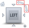
When the ViewCube tool is active while viewing a model from one of the face views, four orthogonal triangles display near the ViewCube tool. Use these triangles to switch to one of the adjacent face views.
You can also click and drag the ViewCube tool to reorient the view of a model to a custom viewpoint other than one of the twenty-six predefined viewpoints. As you drag, the cursor changes to indicate that you are reorienting the current view of the model. If you drag the ViewCube tool close to one of the preset orientations and it is set to snap to the closest view, the ViewCube tool rotates to the closest preset orientation.
The outline of the ViewCube tool helps you identify the form of orientation it is in: freeform or constrained. When the ViewCube tool is in freeform orientation, not orientated to one of the twenty-six predefined views, its outline displays dashed. The ViewCube tool is outlined in a solid continuous line when it is constrained to one of the predefined views.
To interactively reorient the view
 , and drag in the direction that you want to orbit the model.
Define and restore the Home view
The Home view is a special view stored with a model that makes it easy to return to a known or familiar view. You can define any view of the model as the Home view. Apply the saved Home view to the current view by clicking the Home button above the ViewCube tool.
The default Home position is the existing orientation of the default 3D view.
To reorient the model to the Home view
 ) located near the ViewCube tool.
The ViewCube tool supports three different view projections: perspective, orthographic, and perspective with orthographic faces. When you change the view for a model, the view updates using the selected projection mode.
To change the view projection mode
Control the appearance and behavior of ViewCube
The ViewCube tool displays in one of two states: inactive and active. When the ViewCube tool is inactive, it appears partially transparent by default so that it does not obscure the view of the model. When active, it is opaque and may obscure the view of the objects in the current view of the model.
In addition to controlling the inactive opacity level of the ViewCube tool, you can also control the size and position of the tool:
To control the appearance of the ViewCube tool
When the cursor is in the vicinity of the ViewCube, the cube and all the additional controls are displayed, fully opaque. However, when the cursor is distant from the ViewCube, the additional controls (except the Home button) do not display; the ViewCube and the Home button may display at reduced opacity. Set the opacity display when the cursor is distant (inactive) from the ViewCube.
Select this option to maintain the up direction of the scene.
While being dragged, the ViewCube and the model rotate. If Snap to closest view is selected, the viewpoint will snap to one of the fixed views when it is angularly close to one of the fixed views.
The NavBar is available for use when the ViewCube is selected as the View control in the Viewing section of Preferences > General Preferences❒.
+ . (also + Command on the Mac).
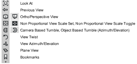
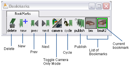
Of special interest are the following tools:
Clicking the Look at icon centers the view and zooms in on the selected objects (or all objects if nothing is picked). See also Center the view on specific objects.
Return the view to the previous view.
Switch between orthographic and perspective views.
Scale the view independently along the horizontal and vertical axes. After you click this tool, the interaction depends on the setting of Non proportional scaling box in General Preferences.
If this option is checked on, click and drag to draw a box on the screen around the area you want to examine. When you release the mouse button, the window fills with the content of the box.
If this option is unchecked, drag the mouse to scale the view interactively. Drag the left and right to scale the view horizontally, and up and down to scale the view vertically.Drag the  to scale the view horizontally only. Drag the
  to scale the view vertically only.
Switch between proportional and non-proportional views. See Toggle between proportional and non-proportional views.
Lets you track, dolly, and tumble the view using different mouse buttons. Press + (also + on the Mac) and drag the mouse button as follows:
: Tumble
: Track
: Dolly
Lets you revolve, track, dolly, and twist the view using different mouse buttons. Press + (also + on the Mac) and drag the mouse button as follows:
: Azimuth/Elevation
Dragging the mouse across the whole window (either horizontally or vertically) rotates the view 180 degrees.
: Track
vertical drag: Dolly
horizontal drag: Twist
See:
When Camera Based Tumble is selected, turns the perspective view in the viewing plane as if you are watching the scene while tilting your head to
the side. Press + (also + on the Mac), click the tool and then click-drag the .
Dragging the mouse to the right rotates the view counter-clockwise, and dragging to the left rotates the view clockwise. Dragging across the whole window rotates the view 360 degrees.
When Camera Based Tumble is selected, revolves the camera about the point of interest in the perspective view. Press + (also + on the Mac), click the tool and then click-drag the mouse to revolve the view.
To revolve the view both horizontally and vertically, click-drag the .
To revolve the view horizontally only, click-drag the .
To revolve the view vertically only, click-drag the .
Dragging the mouse across the whole window (either horizontally or vertically) rotates the view 180 degrees.
Clicking Plane View lets you tumble about the currently active construction plane (that is, the construction plane is used as the ground plane).
As you work on the model, you typically change the camera view back and forth between two or more areas of interest. The NavBar lets you “bookmark” views of the model and return to those views by clicking the name of the bookmark.
Additionally, shading attributes (from the Diagnostic Shading panel or WindowDisplay > Hardware Shade ), and annotations (created using tools in the Paint tab) are stored in bookmarks.
When switching from one bookmark (or view) to the next, the camera is animated to take you smoothly from one view to another without getting disoriented.
Add a bookmark for the current view using the NavBar
+ (also + on the Mac).
Edit a bookmarked view from the NavBar
+ (also + on the Mac).
 + (also + on the Mac) and do any of the following in the Bookmark Lister:
 (Windows) or
  (Mac) and double-click the bookmark icon. Type a new name in the dialog box, then click OK.
.
(Mac) and double-click the bookmark icon. Type a new name in the dialog box, then click OK.
.


