How to build a PDA using and .
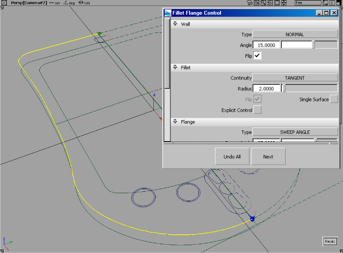
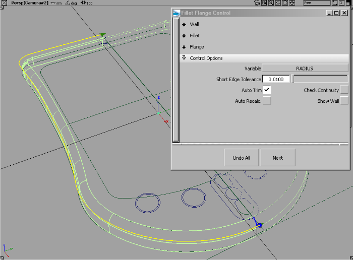
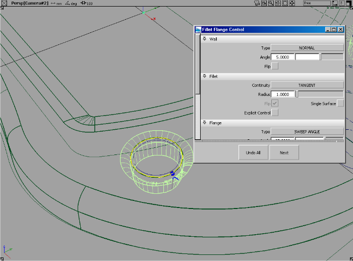
- Choose Surfaces > Rolled Edge > Fillet Flange
 ❒, then click the trimmed edge of the top surface.
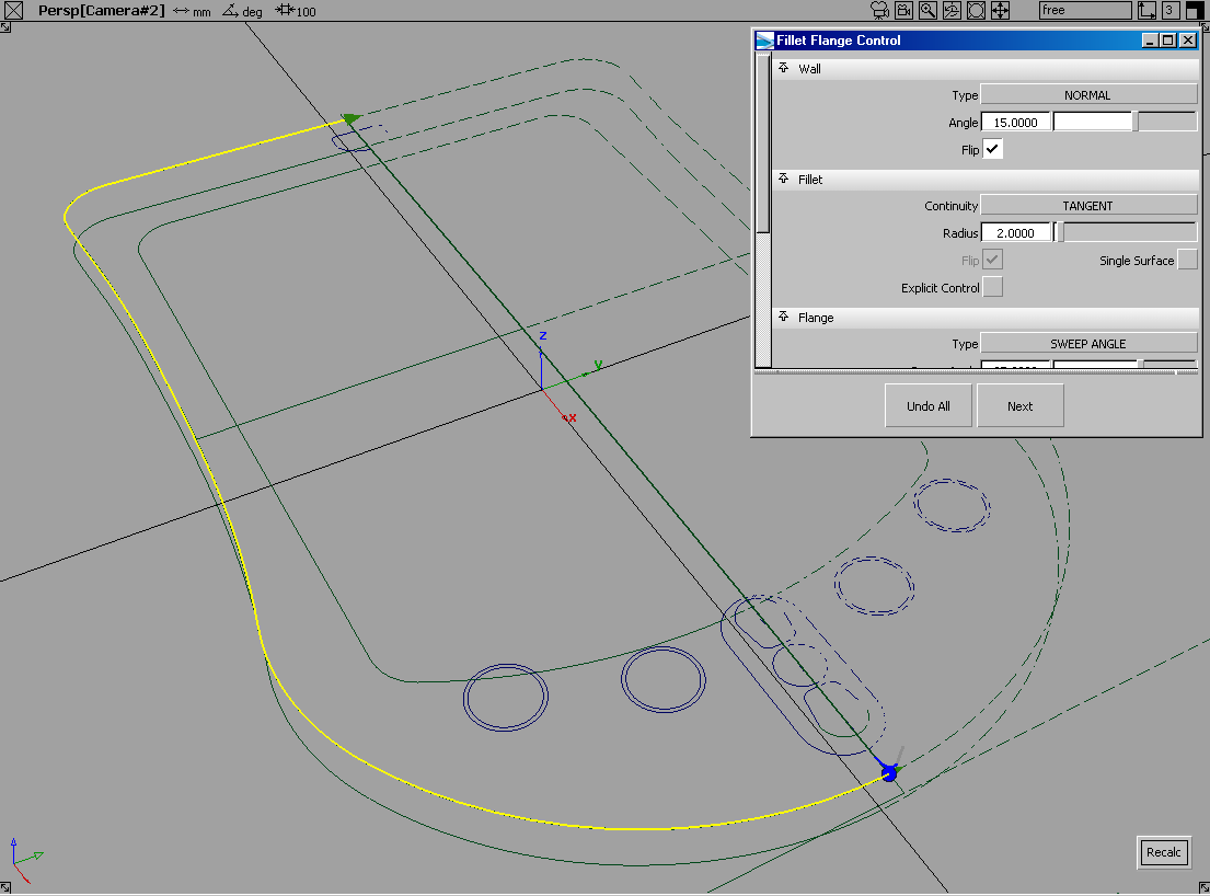
- You may find that the fillet flange builds in the wrong direction, based on the curve direction. To change the direction,
choose in the section of the control window.
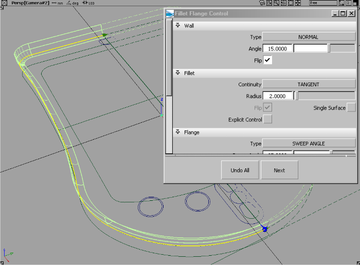
In this example we have set a 15 degree taper on the wall and a two unit fillet. You should notice immediately this tool first
builds a flange wall, and then fillets between the flange wall and the input surface in one very simple workflow.
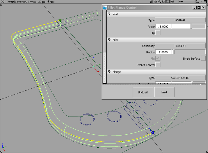
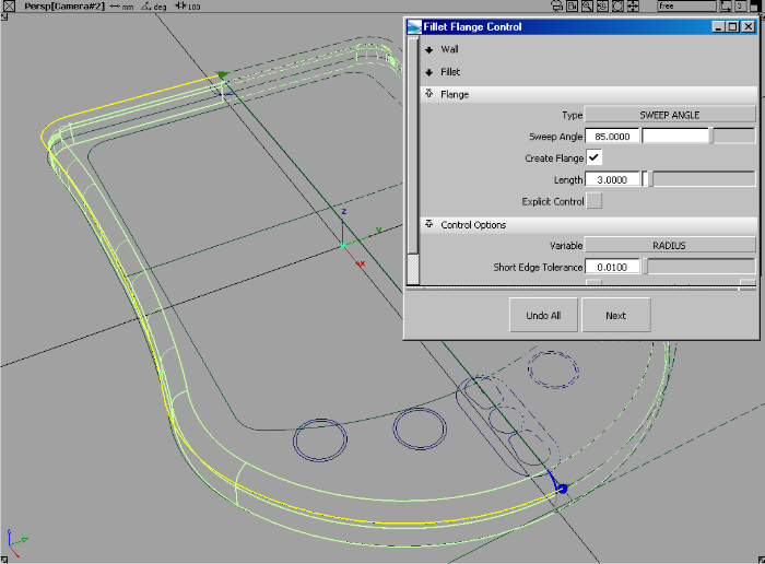
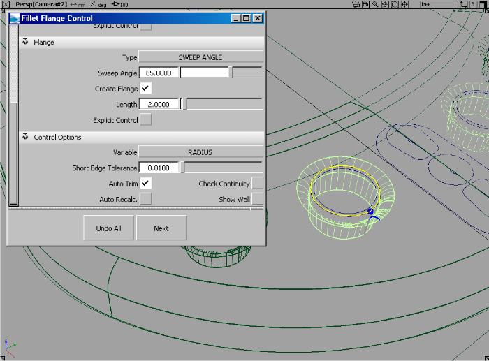
- Adjust the length of the flange then click the button.
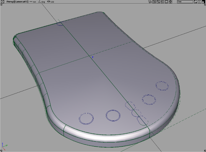
- When you have completed adjusting the fillet and flange properties, turn on so the top surface is automatically trimmed.
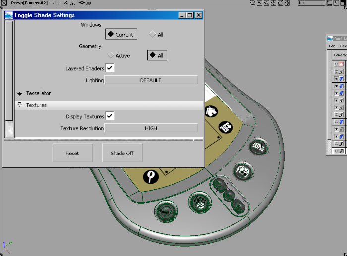
- Turn on WindowDisplay > Hardware Shade
 to evaluate the surfaces.
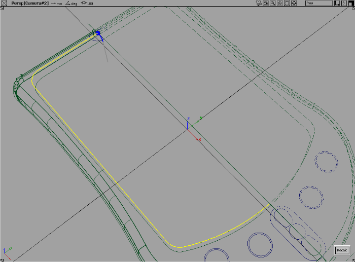
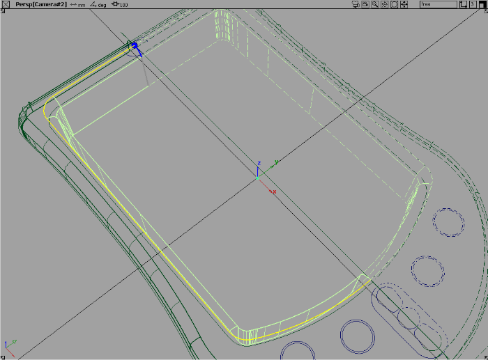
- In the view, project the curves on the inside that will define the LED display area.
- Use the trim tool to discard the center of the surface, resulting in surfaces as shown here.
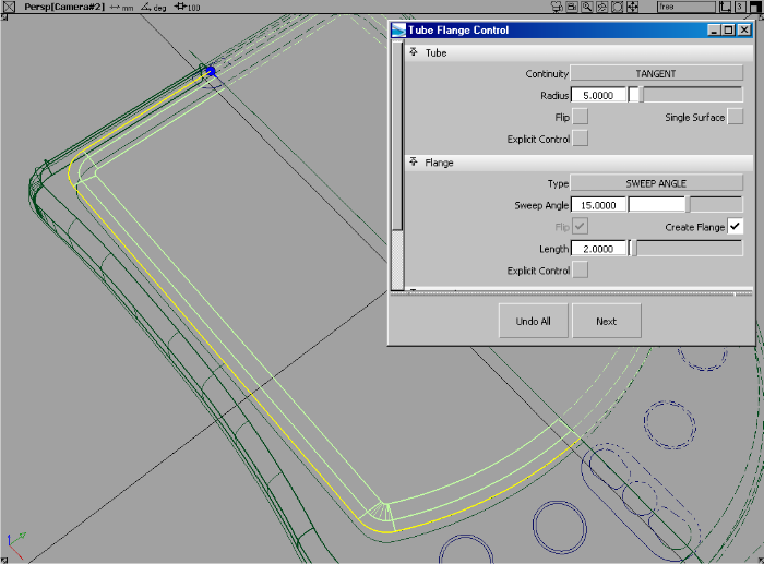
- Use Surfaces > Rolled Edge > Tube Flange
 to create a blended inner surface for the LED area.
- Tube flange prompts you to select a series of curves. In this example, we create a fillet (tube) then draft a flange from
the edge of the fillet. This complex operation is done with one simple workflow using the Tube flange tool.
By default, the tube is 1 unit and the flange is built at 90 degrees.
- In the control window, adjust the Fillet size to 5, Flange sweep angle to 15, and the Flange length to 2.
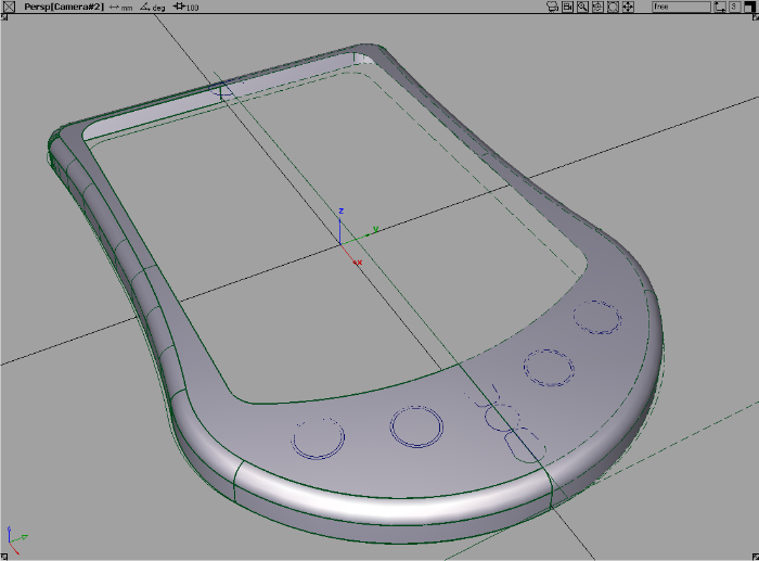
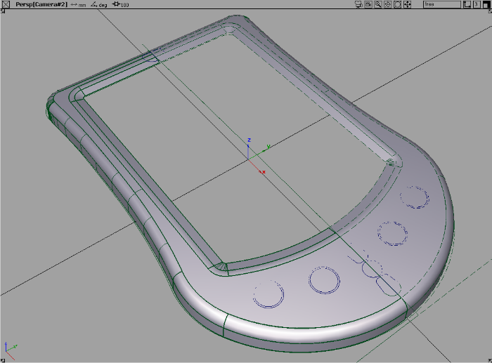
- Turn on to review the surfaces.
Building button holes and buttons
- In the top window project the circles that will form the button holes.
- Using the trim surface tool, discard the holes in the top surfaces.
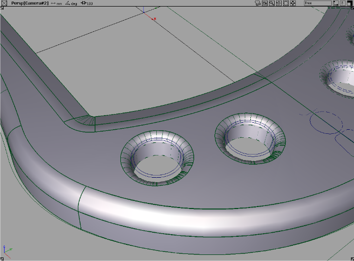
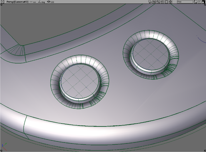
- Use Surfaces > Rolled Edge > Fillet Flange to create the blend recesses for the buttons.
- Repeat this the fillet flange process for the second button.
- Turn on to review the button recess.
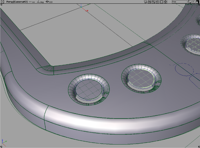
- Choose Surfaces > Planar Surfaces > Set Planar
 to create the tops of the buttons using simple circle curves.
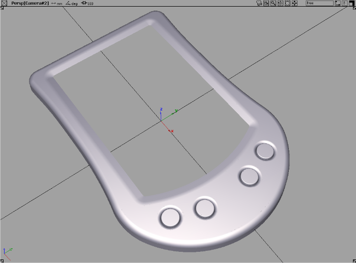
- Choose Surfaces > Rolled Edge > Tube Flange to create the filleted flange surfaces that are needed for the button edges.
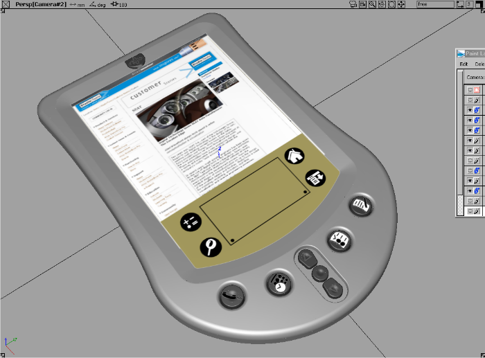
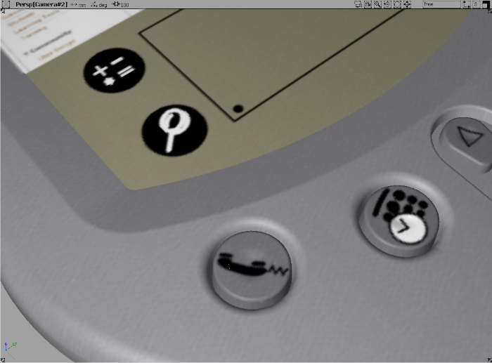
- Dolly the camera out to review the surfaces created so far.
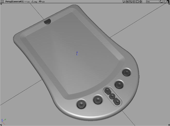
- Refine the surface design and add more detail, like buttons for other functions.
Finishing the concept model
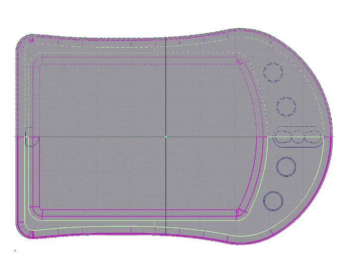
Next, we’ll add some graphic design detail to our concept model. In this example we have turned off the gray plastic paint
layer and selected all the surfaces highlighted in red.
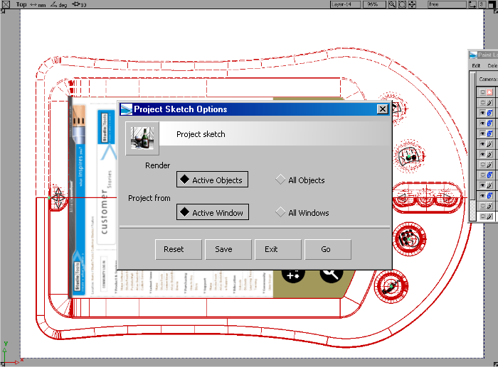
- Open the Canvas > Project Sketch
 options window, select and , then click .
- In the options window, make sure layered shaders is turned on.
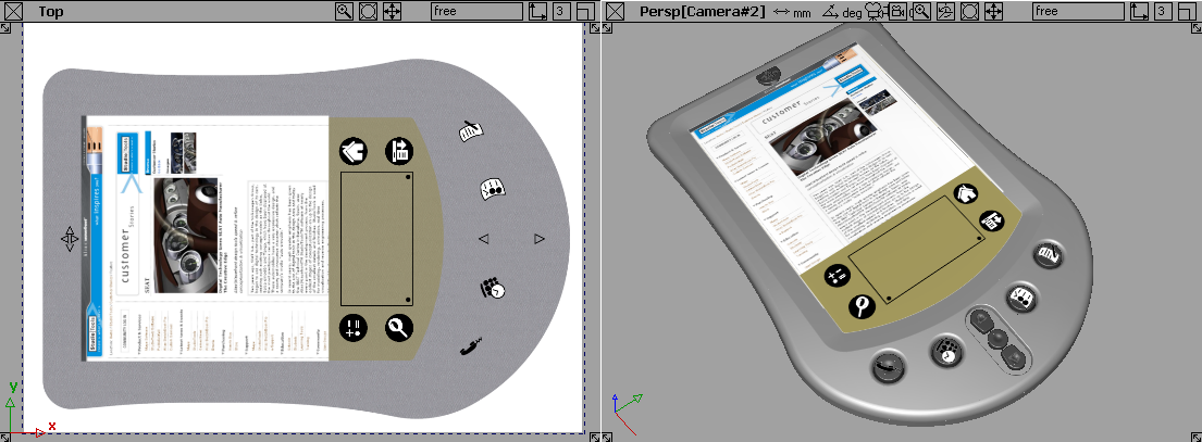
Originally, we created the quick concept sketch using a texture brush to create a plastic finish for the PDA.
- Open the Windows > Editors > Canvas Layer Editor
 and turn this layer back on.
- Choose in the to update the projected shader.
Here is a close-up to show the faint plastic finish painted on the 2D image layer.
- You can now set up the scene for raytracing and produce a simple design image like this. All complex texture mapping is handled
by the Sketch projection procedure.