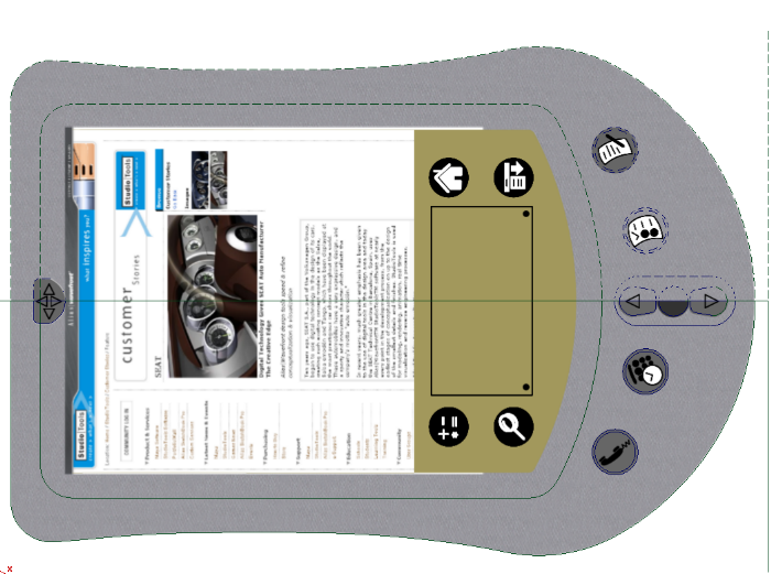
This section will cover how to use sketch projection for texture mapping a typical product design. In the past, texture map placement across multiple trimmed surface was challenging, but this is now much easier with current sketch projection techniques.
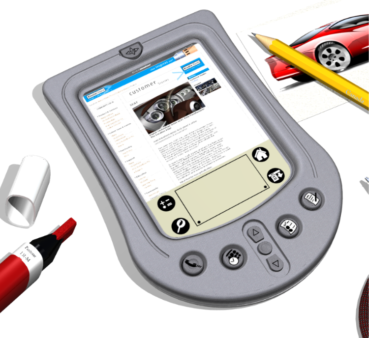
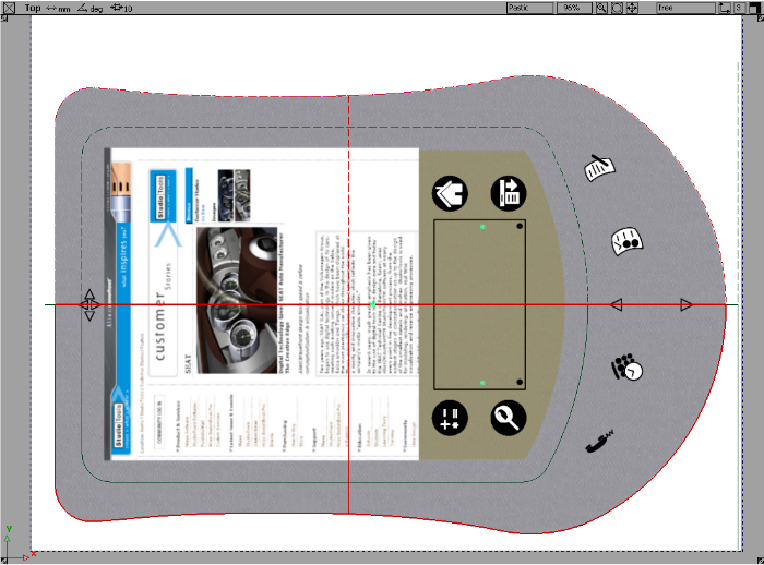
This example image use sketch projection for the small PDA button icons, PDA display, and red sketch. The scene is rendered using Alias RayTracing.
 )and make this layer semi-transparent by changing the
  value.
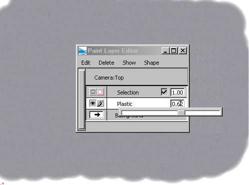
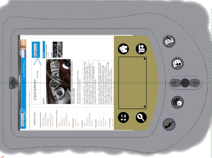
Next, clean up the appearance of the gray base plastic layer. We could use a mask layer and delete the plastic outside the main PDA body, but in this case, we will use an invisibility mask shape to hide the paint on this layer.
Make sure the current layer is the plastic body layer that was painted with the texture brush.
 . You are prompted to select the curves, then click Accept.
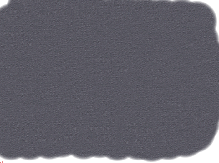
The image below shows how the invisibility mask shape has hidden the paint inside the curves.
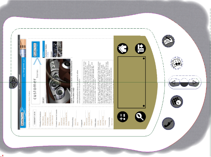
The image above shows how the plastic paint layer now only shows paint defined by the invisibility mask shape. The advantage to this workflow is the paint will be automatically hidden or shown as the curves are modified. If we had used a mask layer and erased the paint with a brush, it would require a significant amount of work to repair the layer.
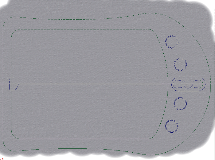
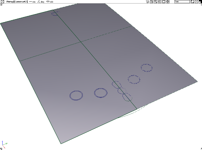
Develop a surface for the model
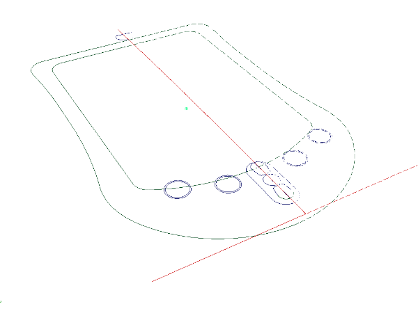
You now have built the primary surface for the PDA top.
 to create curves on surface.
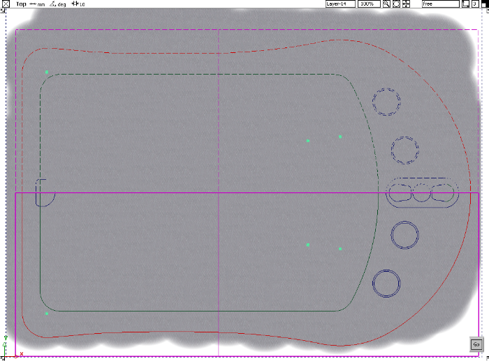
 to cut away the top surface and discard the outer edges.
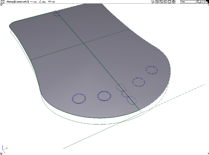
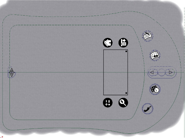
Project painted details on a simple model
From the Top view, we can quickly project paint onto the top surface.
 . This tool supports projection of paint from a number of views and onto active or all surfaces.
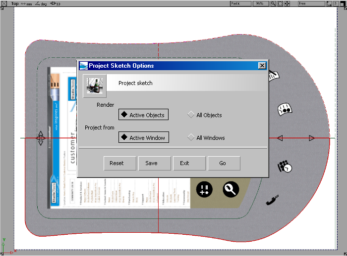
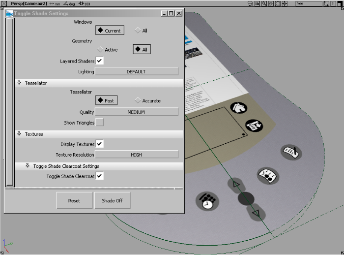
 ❒ to toggle shade on.
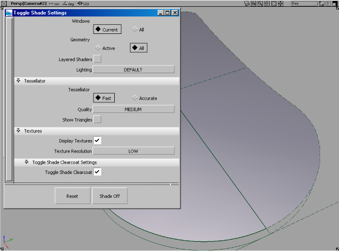
Hardware Shade has been dramatically enhanced in terms of texture quality, speed and the ability to support layered shaders with transparency.