Command entry:
Modify panel

Select a 2D shape.
Modifier List
Sweep
Command entry:Select a 2D shape.
Modifiers menu
Patch/Spline Editing
Sweep
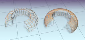
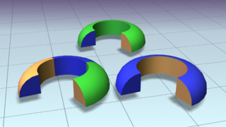
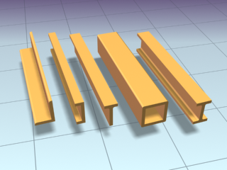
You use the Sweep modifier to extrude a cross-section along an underlying spline or NURBS curve path. It is similar to the
Loft compound object but is more efficient. You can work with a series of pre-made cross-sections such as angles, channels
and wide flanges, and can also use your own splines or NURBS curves as custom sections.
NoteThis modifier is similar to the Extrude modifier in that once the Sweep is applied to a spline, the end result is a 3D mesh
object. Both sections and paths can contain multiple splines or multiple NURBS curves.
This modifier is very useful for creating structural steel details, molding details, or in any situation where you need to
extrude a section along a spline.
Procedures
To apply the Sweep modifier to a line:
- In the Perspective viewport, create a line.
- Apply the Sweep modifier to the line.
The line takes on the shape of an angled extrusion.
- Open the Built-In Section list and choose a different section.
The line now has the new section swept along its length.
To use a custom section with the Sweep modifier:
- Create a line and a six-sided NGon in the perspective viewport.
- Apply the Sweep modifier to the line.
The line takes on the shape of an angled extrusion.
- Click the Use Custom Section radio button.
The line displays as a line again.
- Click the Pick button in the Custom Section Types group and choose the NGon in the viewport.
The hexagonal shape is swept along the line's length.
NoteIf you find that you need to rescale the Custom Section shape, the effects of using a transform like Select and Squash or
Non-Uniform Scale will not be reflected when swept. You need to apply an
XForm modifier to the section and then rescale the XForm modifier's gizmo.
Interface
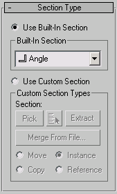
Section Type rollout
- Use Built-In Section
-
Choose this to use one of the included stock sections.
Built-In Section group
- Built-In Section list
-
- Use Custom Section
-
Choose this if you've created your own section or there is another shape in the current scene or in another MAX file that
you'd like to use as your section.
NoteUsing a 2D shape as the Sweep modifier’s custom section will yield the most predictable results. If using a 3D shape as the
custom section, for the most predictable results the base object should be a straight line or smooth path like a circle or
an arc. The same applies to custom sections made up of multiple splines. You'll get the best results attained by insuring
that all vertices in all the shapes are coplanar.
Custom Section Types group
- Section
-
Displays the name of the custom shape you've selected. This area is blank until you select a custom shape.
NoteYou can switch from a custom section to a built-in section and back without having to pick the custom-section shape again
from the viewports.
- Pick
-
If the custom shape you want to use is visible in the viewport, click the Pick button and then pick the shape directly from
the scene.
- Pick Shape
-
Click the Pick Shape button to open the Pick Shape dialog. This dialog shows only valid shapes that are currently in the scene.
- Extract
-
Lets you create a new shape in the scene that is either a copy, instance, or reference of the current custom section. Opens
the Extract Shape dialog.
- Merge From File
-
Lets you choose a section that is stored in another MAX file. Opens the Merge File dialog.
NoteWhen you use the Merge from File option, you will not be able to Undo your work.
- Move
-
Sweeps the custom section along the specified spline. Unlike the Instance, Copy and Reference switches, the selected section
is moved to the spline. Editing the original shape in the viewports has no effect on the Sweep mesh.
- Copy
-
Sweeps a copy of the selected section along the specified spline.
- Instance
-
Sweeps an instance of the selected section to the specified spline.
- Reference
-
Sweeps a reference of the selected section along the specified spline.
NoteWhen using Instance or Reference, adding modifiers to or editing the original section in the viewports will change the Sweep
mesh.
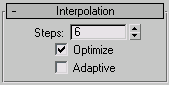
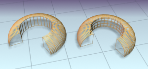
Interpolation rollout (Sweep modifier)
The controls in the Interpolation rollout of the Sweep modifier work exactly as they do for any other spline. However, the
controls affect only the built-in section you've chosen, not the spline that the section is swept along.
NoteIf you want to change the interpolation settings of the underlying spline path, you need to select the path object in the
modifier stack.
In general, all spline curves are divided into small straight lines that approximate a true curve. The number of divisions
between each vertex on the spline are called steps. The more steps used, the smoother the curve appears.
NoteThe Interpolation rollout is only active when built-in sections are used.
- Steps
-
Sets the number of divisions, or steps, 3ds Max uses between each built-in section's vertices. Splines with tight curves require many steps to look smooth while gentle curves
require fewer steps. Range=0 to 100.
Spline steps can be either adaptive or manually specified. The method used is set by the state of the Adaptive switch. The
main use for manual interpolation is to create splines for morphing or other operations where you must have exact control
over the number of vertices created.
- Optimize
-
When on, removes unneeded steps from straight segments in the spline. Default=on.
NoteOptimize is not available when Adaptive is on.
- Adaptive
-
When on, automatically sets the number of steps for each spline to produce a smooth curve. Straight segments always receive
0 steps. When off, enables manual interpolation control using Optimize and Steps. Default=off.
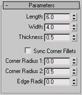
Parameters rollout
The Parameters rollout is context-sensitive and displays different settings depending upon the built-in section you've chosen
to sweep along a spline. For example, more complex sections such as the Angle have seven settings that you can change whereas
the Quarter-Round has only one setting.
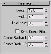
Parameters rollout: Angle
- Length
-
Controls the height of the vertical leg of the angle section. Default=6.0.
- Width
-
Controls the width of the horizontal leg of the angle section. Default=4.0.
- Thickness
-
Controls the thickness of both legs of the angle. Default=0.5.
- Sync Corner Fillets
-
When turned on, Corner Radius 1 controls the radius of both the interior and exterior corners between the vertical and horizontal
legs. It also maintains the thickness of the section. Default=off.
- Corner Radius 1
-
Controls the exterior radius between the vertical and horizontal legs of the angle section. Default=0.0.
- Corner Radius 2
-
Controls the interior radius between the vertical and horizontal legs of the angle section. Default=0.5.
- Edge Radii
-
Controls the interior radius at the outermost edges of the vertical and horizontal legs. Default=0.0.
NoteBe cautious when adjusting these settings. There are no constraining relationships between them. Therefore, it's possible
to set an inside radius (Corner Radius 2) that is greater than the length or width of the legs of the angle.
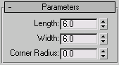
Parameters rollout: Bar
- Length
-
Controls the height of the bar section. Default=6.0.
- Width
-
Controls the width of the bar section. Default=6.0.
- Corner Radius
-
Controls the radius of all four corners of the section. Default=0.0.
Parameters rollout: Channel
- Length
-
Controls the height of the vertical web of the channel section. Default=12.0.
- Width
-
Controls the width of the top and bottom horizontal legs of the channel section. Default=4.0.
- Thickness
-
Controls the thickness of both legs of the channel. Default=0.5.
- Sync Corner Fillets
-
When on, Corner Radius 1 controls the radius of both the interior and exterior corners between the vertical web and horizontal
legs. It also maintains the thickness of the section. Default=off.
- Corner Radius 1
-
Controls the exterior radius between the vertical web and horizontal legs of the channel. Default=0.0.
- Corner Radius 2
-
Controls the interior radius between the vertical web and horizontal legs of the channel. Default=0.5.
NoteBe cautious when adjusting these settings. There are no constraining relationships between them. Therefore, it's possible
to set an inside radius (Corner Radius 2) that is greater than the length of the web or width of the legs.
Parameters rollout: Cylinder
- Radius
-
Controls the radius of the cylinder section. Default=3.0.
Parameters rollout: Half-Round
- Radius
-
Controls the radius of the half round section. Default=3.0.
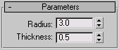
Parameters rollout: Pipe
- Radius
-
Controls the exterior radius of the pipe section. Default=3.0.
- Thickness
-
Controls the thickness of the wall of the pipe. Default=0.5.
Parameters rollout: Quarter-Round
- Radius
-
Controls the radius of the quarter round section. Default=3.0.
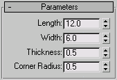
Parameters rollout: Tee
- Length
-
Controls the height of the vertical web of the tee section. Default=12.0.
- Width
-
Controls the width of the flange crossing the tee section. Default=6.0.
- Thickness
-
Controls the thickness of the web and flange. Default=0.5.
- Corner Radius
-
Controls the radius of the two interior corners between the vertical web and horizontal flange of the section. Default=0.5.
NoteBe cautious when adjusting these settings. There are no constraining relationships between them. Therefore, it's possible
to set a radius (Corner Radius) that is greater than the length of the web or width of the flange.
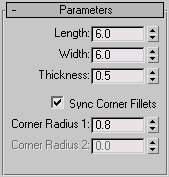
Parameters rollout: Tube
- Length
-
Controls the height of the tube section. Default=6.0.
- Width
-
Controls the width of the tube section. Default=6.0.
- Thickness
-
Controls the thickness of the walls of the tube. Default=0.5.
- Sync Corner Fillets
-
When turned on, Corner Radius 1 controls the radius of both the interior and exterior corners of the tube. It also maintains
the thickness of the section. Default=on.
- Corner Radius 1
-
Controls the radius of all four interior and exterior corners of the section. Default=0.8.
If Sync Corner Fillets is turned off, Corner Radius 1 controls the radius of the four exterior corners of the tube.
- Corner Radius 2
-
Controls the radius of the four interior corners of the tube. Default=0.0.
Corner Radius 2 is only available when Sync Corner Fillets is turned off.
NoteTake care when adjusting these settings. There are no constraining relationships between them. Therefore, it's possible to
set an inside radius (Corner Radius 2) that is greater than the length and width of the sides.
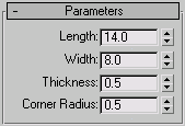
Parameters rollout: Wide Flange
- Length
-
Controls the height of the vertical web of the wide flange section. Default=14.0.
- Width
-
Controls the width of the horizontal flanges crossing the section. Default=8.0.
- Thickness
-
Controls the thickness of the web and flanges. Default=0.5.
- Corner Radius
-
Controls the radius of the four interior corners between the vertical web and horizontal flanges. Default=0.5.
NoteBe cautious when adjusting these settings. There are no constraining relationships between them. Therefore, it's possible
to set a radius (Corner Radius) that is greater than the length of the web or width of the flanges.
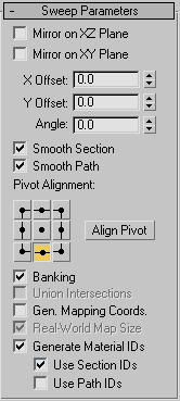
Sweep Parameters rollout
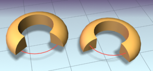
- Mirror On XZ Plane
-
When turned on, the section is flipped vertically in relation to the spline to which the Sweep modifier is applied. Default=off.
- Mirror On XY Plane
-
When turned on, the section is flipped horizontally in relation to the spline to which the Sweep modifier is applied. Default=off.
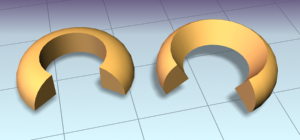
- X Offset
-
Lets you shift the horizontal position of the section relative to the underlying spline.
- Y Offset
-
Lets you shift the vertical position of the section relative to the underlying spline.
NoteThe X and Y Offsets let you fine tune the section position while the Pivot Alignment settings allow for a quick initial adjustment.
- Angle
-
Allows you to rotate the section relative to the plane on which the underlying spline is located.
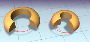
- Smooth Section
-
Provides a smooth surface around the perimeter of the section that is swept along the underlying spline. Default=on.
- Smooth Path
-
Provides a smooth surface along the length of the underlying spline. This type of smoothing is useful when for curved paths.
Default=off.
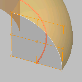
- Pivot Alignment
-
This is 2D grid that helps you align the section to the underlying spline path. Selecting one of the nine buttons shifts the
section's pivot around the spline path.
NoteWhen none of the Pivot Alignment buttons is depressed the pivot point of the section is used as the alignment point.
- Align Pivot
-
When turned on, a 3D representation of the Pivot Alignment grid appears in the viewport. You only see the 3x3 alignment grid,
the section and the underlying spline path. Once you're satisfied with the alignment, turn off the Align Pivot button or right-click
to see the sweep.
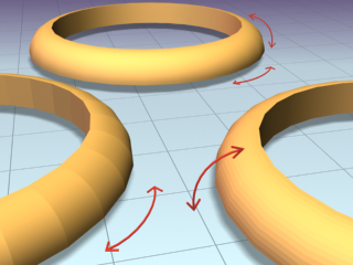
- Banking
-
When on, sections rotate about the spline path whenever the path bends and changes height in the path's local Z axis. Banking
is ignored if the spline path is 2D. When off, shapes do not rotate about their Z axis as they traverse a 3D path. Default=on.
- Union Intersections
-
If working with multiple intersecting splines, like a grid, turn this switch on to produce cleaner intersections with fewer
artifacts.
NoteUnion Intersections takes additional time to compute the intersections, so leave this switch off if you don't have intersecting
splines. Furthermore, this setting will only calculate intersections of separate splines contained in one shape object. So
a figure X (separate, intersecting splines) will be properly intersected, but a figure 8 (a single, self-intersecting spline)
will not.
- Gen. Mapping Coords
-
Applies mapping coordinates to the extruded object. Default=off.
- Real-World Map Size
-
Controls the scaling method used for texture mapped materials that are applied to the object. The scaling values are controlled
by the Use Real-World Scale settings found in the applied material's Coordinates rollout. Default=on.
- Generate Mapping IDs
-
Assigns different material IDs to the sides and the caps of the sweep. Specifically, if both Use Section IDs and Use Path
IDs are both turned off the sides receive ID 3, the front cap receives ID 1, and the rear cap receives ID 2. Default=on.
- Use Section IDs
-
Uses the material ID values assigned to segments of the section that is swept along the underlying spline or NURBS curve. Default=on.
By applying an Edit Spline modifier to a Custom Section, different material IDs can be assigned to each segment that makes up the section.
NoteBuilt-in sections do not benefit from the Use Section IDs switch.
- Use Path IDs
-
Uses the material ID values assigned to segments of the underlying spline or curve sub-objects in the underlying curve.
By applying an Edit Spline modifier to the underlying spline, each segment can be assigned its own material ID.
NoteUse Section IDs and Use Path IDs does not control the material IDs of the front and rear caps of the sweep.
- Pick Shape Dialog (Sweep Modifier)
The Pick Shape dialog is displayed when you select a custom shape in the scene. This shape can be any of the splines, extended
splines or NURBS curves.
- Extract Shape Dialog (Sweep Modifier)
The Extract feature allows you to recover custom cross-sections that may have been deleted from the scene. As long as you
have a Sweep object in the scene that uses the deleted shape as a custom cross-section, you can use Extract to restore the
shape to the scene.
- Merge File (Sweep Modifier)
The Merge File dialog for the Sweep modifier appears when you click the Merge From File button. Merge From File allows you
to bring shapes or section profiles from other scene files into the current scene.
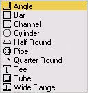
 Angle sectionSweeps a structural angle section along the spline. Default section=Angle.
 Bar sectionSweeps a 2D rectangular section along the spline.
 Channel sectionSweeps a structural channel section along the spline.
 Cylinder sectionSweeps a solid 2D circle section along the spline.
 Half Round sectionThis section produces a half round extrusion along the spline.
 Pipe sectionSweeps a circular hollow tube section along the spline.
 Quarter Round sectionUseful for molding details; this section produces a quarter round extrusion along the spline.
 Tee sectionSweeps a structural tee section along the spline.
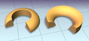
 Tube sectionBased on a square, this sweeps a hollow tube section along the spline. Similar to the Pipe section.
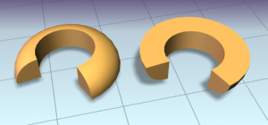
 Wide Flange sectionSweeps a structural wide flange section along the spline.