Command entry:
 Application Menu
References
File Link Manager
File Link Manager dialog
Files panel
Reload a linked DWG/DXF file with Show Reload turned on.
File Link Settings: DWG Files dialog
Basic panel
Command entry: Application Menu References
File Link Manager
File Link Manager dialog
Presets panel
Select an existing DWG/DXF preset and click Modify.
File Link Settings: DWG Files dialog
Basic panel
Command entry: Application Menu References
File Link Manager
File Link Manager dialog
Presets panel
Create a new DWG/DXF preset.
Select the newly created preset and click Modify
File Link Settings: DWG Files dialog
Basic panel
Command entry: 
Utilities panel
Utilities rollout
More button
File Link Manager
File Link Manager dialog
Files panel
Reload a linked DWG/DXF file with Show Reload turned on.
File Link Settings: DWG Files dialog
Basic panel
Command entry: Utilities panel
Utilities rollout
More button
File Link Manager
File Link Manager dialog
Presets panel
Highlight an existing DWG/DXF preset and click Modify.
File Link Settings: DWG Files dialog
Basic panel
Command entry: Utilities panel
Utilities rollout
More button
File Link Manager
File Link Manager dialog
Presets panel
Create a new DWG/DXF preset.
Highlight the newly created preset and click Modify
File Link Settings: DWG Files dialog
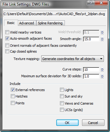
Basic panel
The Basic panel of the File Link Settings: DWG Files dialog defines how 3ds Max converts the linked file’s objects into corresponding 3ds Max objects.
Interface
- Weld nearby vertices
-
Sets whether to weld nearby vertices of converted objects according to the Weld Threshold setting. Welding smooths across
seams and unifies normals of objects with coincident vertices. Welding occurs only on vertices that are part of the same object.
- Weld threshold
-
Sets the distance that determines whether vertices are coincident. If the distance between two vertices is less than or equal
to the weld threshold, the vertices are welded together. To use the Weld Threshold, turn on Weld.
- Auto-smooth adjacent face
-
Assigns smoothing groups according to the Smooth-angle value. Smoothing groups determine whether faces on an object render as a smooth surface or
display a seam at their edges, creating a faceted appearance.
- Smooth-angle
-
Controls whether smoothing occurs between two adjacent faces. If the angle between the two face normals is less than or equal
to the smooth angle, the faces are smoothed (that is, put in the same smoothing group).
- Orient normals of adjacent faces consistently
-
Analyzes the face normals of each object and flips normals where necessary, so they all point in a direction that is consistent
with adjoining faces. If the imported geometry isn't properly welded, or if the AutoCAD geometry did not contain or specify
normal information, normals might be oriented in the wrong direction. Use the Edit Mesh or Normal modifiers to flip normals.
When Unify Normals is off, normals are calculated according to the face vertex order in the linked file. Face normals for
AutoCAD solids are already unified. Turn off Unify Normals when importing only AutoCAD solid models from AutoCAD Architecture.
- Cap closed splines
-
Applies an Extrude modifier to all closed objects, and selects the Cap Start and Cap End options of the modifier. The Extrude modifier Amount value for
a closed object with no thickness is set to 0. Capping makes closed objects with thickness appear solid and closed objects
without thickness appear flat. When Cap Closed Objects is off, the Extrude modifier Cap Start and Cap End options for closed
objects with thickness are clear. No modifiers are applied to closed objects without thickness.
TipUnless you chose the One-to-One sorting option, you won't immediately see the Extrude modifier when selecting an object. To
see it, look through the modifier stack for the
VIZBlock sub-objects. In a nested VIZBlock, the Extrude modifiers appear at the bottom of the stack. You can then edit the Extrude
modifier parameters.
- Texture Mapping
-
The texture mapping setting can reduce the loading time of models that have many objects with stored UVW Coordinates for texture
mapped materials.
NoteThis setting applies only to geometry that is stored as a mesh in the scene. Spline shapes marked as renderable have separate
controls for UVW coordinate generation; these are found on the
Spline Rendering panel.
- Automatically generates UVW coordinates for all objects when the drawing is linked.
This option tells the File Link Manager to create UVW coordinates, but loading time is increased while the coordinate generation
occurs.
- Does not generate texture coordinates for linked mesh objects.
Actively linked objects generate UVW coordinates on demand, so if you assign a material to an object and the material requires
texture coordinates, the texture coordinates are silently assigned to that object. If the material or texture map is set to
display in viewport, the coordinates are assigned as soon as the material is applied; if not, the coordinates are assigned
when the scene is rendered.
This option gives you faster loading speed, but no UVW coordinate generation.
NoteObjects in drawings created in AutoCAD Architecture pass texture coordinates explicitly to 3ds Max when you attach the drawing. If you specify on-demand coordinate generation, they might not match the coordinates that were
specified in the original drawing. The map scaling is the same, but the texture offsets may be altered.
- Curve steps
-
For objects such as splines, the number of knot points determines the spline's shape and curvature. The Curve steps value
defines the number of segments between knot points. A low value gives you a more linear interpolation between the knot points;
a higher number gives you a more accurate curve.
- Maximum surface deviation for 3D solids
-
Specifies the maximum allowable distance from the 3ds Max surface mesh to the parametric AutoCAD solid surface. Small numbers produce more accurate surfaces with a greater number
of faces. Large numbers produce less accurate surfaces with fewer faces.
Include group
This group allows you to toggle the inclusion of specific parts of a DWG file during the file link process.
- External references
-
Imports xrefs attached to the DWG file.
- Lights
-
Imports lights from pre-AutoCAD 2007 DWG files.
- Sun and Sky
-
Imports Sun and Shadows position from the drawing file (AutoCAD / AutoCAD Architecture 2008 and Revit 2008 only).
NoteYou must set mental ray as the default renderer for you to see the Sun and Sky effect. To set mental ray as the default renderer,
see
Choose Renderer Dialog.
- Hatches
-
Imports hatches from the DWG file.
WarningThis stores each line or dot in the hatch pattern as a separate spline that defines the hatch; this can create a very large
number of objects in your scene.
- Views and Camera
-
Imports named views from the DWG file, and converts them to 3ds Max cameras.
NoteOrthographic views do not translate correctly in imported DWG files. However, there are no problems with Perspective views.
- Points
-
Imports points from the DWG file.
NoteThe imported point objects are represented in
3ds Max as
Point Helper objects.
- UCSs (grids)
-
Imports user coordinate systems (UCS) from the DWG file and converts them to 3ds Max grid objects.