 Command entry:
 Application Menu
  References File Link Manager File Link Manager dialog Files panel Reload a linked DWG/DXF file with Show Reload turned on. File Link Settings: DWG Files dialog Advanced panel
Command entry: Application Menu References File Link Manager File Link Manager dialog Presets panel Select an existing DWG/DXF preset and click Modify. File Link Settings: DWG Files dialog Advanced panel
Command entry: Application Menu References File Link Manager File Link Manager dialog Presets panel Create a new DWG/DXF preset. Select the newly created preset and click Modify File Link Settings: DWG Files dialog Advanced panel
Command entry:
References File Link Manager File Link Manager dialog Files panel Reload a linked DWG/DXF file with Show Reload turned on. File Link Settings: DWG Files dialog Advanced panel
Command entry: Application Menu References File Link Manager File Link Manager dialog Presets panel Select an existing DWG/DXF preset and click Modify. File Link Settings: DWG Files dialog Advanced panel
Command entry: Application Menu References File Link Manager File Link Manager dialog Presets panel Create a new DWG/DXF preset. Select the newly created preset and click Modify File Link Settings: DWG Files dialog Advanced panel
Command entry:  Utilities panel Utilities rollout More button File Link Manager File Link Manger dialog Files panel Reload a linked DWG/DXF file with Show Reload turned on. File Link Settings: DWG Files dialog Advanced panel
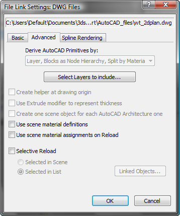
The Advanced panel of the File Link Settings: DWG Files dialog controls how 3ds Max derives AutoCAD primitives and whether 3ds Max uses the scene material definitions when linking to or reloading the AutoCAD drawing. It also lets you selectively reload your scene, so that you reload only specific objects, not the entire file.
Lists the options for deriving objects from the linked DWG file. This setting is available only when modifying a preset.
There are six options to choose from:
Each block is linked separately as a hierarchy, with the block itself as the parent object and its constituent parts as child objects. The child objects of the block are combined by layer.
For example, take an AutoCAD file with six objects in layer A: three have a Brick material and three have a Stone material. Using this option, this file would be linked to in the form of two objects, or nodes, one containing the Brick material and the other with the Stone material.
Each block is linked to separately as a hierarchy, with the block itself as the parent object and its constituent parts as child objects. The child objects of the block are combined by layer.
On import, ACIS solids and polymesh geometry can support multiple materials. For polymesh geometry, one material is supported per face. For an ACIS solid, if the solid has more than one material associated with it, a multi/sub object material is created that contains the materials used. If the solid has only one material associated with it, a standard/architectural material is assigned instead.
One benefit of this option is that you can apply instanced animation controllers to block subcomponents and thus, by transforming a single member, transform all members at once. For example, in a scene containing a conference table with six chairs around it, you could move all of the chairs simultaneously by moving a single chair.
Another advantage is that all geometry is instanced, so edited UVs and normals and other modifications need be done only once.
Multiple materials per object are supported with this option, if needed. If the object is an ACIS solid, and has more than one material associated with it, a multi/sub object material is created containing the materials that can be edited in the Materials Editor. If the solid has only one material associated with it, a standard/architectural material is assigned instead. If the object is polymesh geometry, one material per face is supported.
Displays the Select Layers dialog, which you use to choose layers to import from the linked file. Available only when reloading a linked file.
When on, 3ds Max inserts the user coordinate system icon as an origin point helper. 3ds Max places this helper at the world origin of the linked file. It's a reference point for all the geometry of the linked file. After attaching, the helper is selected, allowing you to easily move, rotate, or scale all the geometry that was just added to the scene. Each linked file gets a unique helper object.
This setting is available only when modifying a preset.
When on, linked objects with thickness receive an Extrude modifier to represent the thickness value. You can then access the parameters of this modifier and change the height segments, capping options, and height value.
When off, objects with thickness (and closed capped objects) are converted directly to a mesh.
This setting is available only when modifying a preset, and not using the Derive option Layer, Blocks as Node Hierarchy.
AutoCAD Architecture (formerly Architectural Desktop or ADT) objects are linked as a single object instead of being separated into their constituent components. This means that if you link an AutoCAD Architecture door object, the door is represented as one object instead of three. Turning on this switch make linking faster and the scene size is smaller.
This setting is available only when modifying a preset.
When on, 3ds Max checks the current scene for any currently used materials with the exact same name as a material name in the linked DWG file. If a match is found, File Link does not translate the drawing’s material, but instead uses the material defined in the scene.
When off, the File Link Manager always uses the material definitions contained in the DWG file, and will overwrite scene materials with the same name, regardless of which objects the material is applied to. All material definitions stored in the DWG file are reloaded (even when using a selective reload). If you make changes to a linked material, in 3ds Max, then reload, those changes will be lost (if the switch is off).
If Use Scene Material Assignments on Reload is on at the same time as Use Scene Material Definitions, standard/architectural materials, material assignments, and face material IDs are left as they are.
If Use Scene Material Assignments on Reload is off at the same time as Use Scene Material Definitions, only the material assignments and face material IDs are updated and standard/architectural materials are not translated.
When on, linked objects with a material already assigned to them in the 3ds Max scene will not have that material assignment changed. This is the case regardless of whether the material was assigned automatically by the File Link Manager or manually by the user.
When off, linked objects have their material assignment “coordinated” with the drawing, so that the two are in sync.
If Use Scene Material Definitions is on at the same time as Use Scene Material Assignments on Reload, standard/architectural materials and material assignments are left unchanged.
If Use Scene Material Definitions is off while Use Scene Material Assignments on Reload is on, only standard/architectural materials are retranslated. Any material assignments and Face Material IDs are left unchanged, so Multi/Sub object materials are not retranslated but some sub-materials may have changed.
Lets you perform a partial reload of your linked file. Use a partial reload when you know what has changed in the linked file, and want to speed up the time it takes to reload the geometry.
The following options are available:
Allows you to reload only objects that you choose from a named list. The list is created from the objects linked in the file. When you click Linked Objects, the Select Linked Object dialog is displayed.


