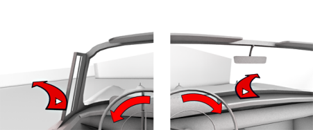
As a driver, when you use a steering wheel to initiate a turn, your eyes tend to follow the direction of the turn. When you turn left, you look left: when you turn right, you look right. In this lesson, your final task is to make the viewpoint of the driver react to the rotation of the steering wheel.
Change the driver’s point of view:
In this procedure, you will wire the rotation of the “driver view” camera to the steering wheel.
 Display panel
  Hide By Category rollout,
turn off Cameras to re-display the cameras in the scene.
Hide By Category rollout,
turn off Cameras to re-display the cameras in the scene.
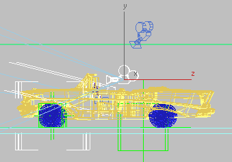
Camera_Driver object
The List Con script automatically adds position and rotation list controllers, permitting you to retain control over the camera’s local orientation.
Notice that the swivel axis needed for the camera is the Y axis (displayed in green).
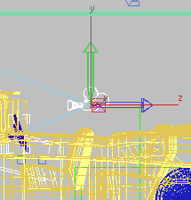
Camera swivel on Y axis
Rotation (2nd) Euler XYZ Z Rotation.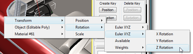
Rotation (2nd) Euler XYZ Y Rotation.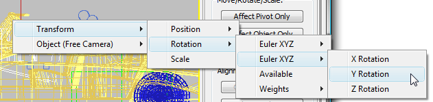
Camera_Driver.
As the steering wheel rotates, the camera viewpoint swivels in the wrong direction.
 Close the Wiring Parameters
dialog and scrub the animation again.
Close the Wiring Parameters
dialog and scrub the animation again.
The rig is now complete.
To view a version of the finished product,  open car_rig_final.max.
In this tutorial, you learned how to assign controllers to components of a model, and use expressions to ensure the controllers animate the components correctly. You also learned how to use Point helpers to animate a model along a path and were shown how to rework the model hierarchy so that a child object can respond to the animation of its parent.


