You can control contour detection — or inking — at global and local levels. Global inking is controlled by the Toon Ink Lens shader, which must be applied to any cameras that you are using to render the toon effect. If the Lens shader is not applied, you cannot render ink lines.
Local inking is controlled by the Toon Host shader, which is available separately or as part of the Toon Paint and Host material shader. The Toon Host shader does not control the full range of ink attributes, but is useful for refining the ink lines created by the Toon Ink Lens shader.
If you want to render ink, you need to apply a Toon Ink Lens shader to any cameras that you'll be using to render the toon effect. Unless you specify otherwise, this renders contours over all scene objects, whether they are toon-shaded or not.
Select one or more of the cameras that render the scene and display its property editor (Modify Shader).
On the Lens Shaders tab, the lens shader stack appears. Click Add to open a browser.
From the shader library, select the Toon_Ink_Lens lens shader from the Lens folder and click OK to attach the shader to the selected camera.
Open the lens shader's property editor by selecting it from the shader stack and clicking the Inspect button.
If you want to change the ink properties of specific objects, you need to apply a Toon Host shader to those objects. This allows you to change the characteristics of those objects' ink lines without changing the global inking created by the Toon Ink Lens shader.
The Toon Host is available by itself or as part of the Toon Paint and Host material shader.
Having a Toon Host shader applied to specific objects allows you to limit the Toon Ink Lens shader's ink rendering to those objects by making the Toon Host shader a requirement for any ink rendering.
Make sure that the Toon Host or Toon Paint and Host shader is applied to those objects that you want to ink.
Select the camera to which the Toon_Ink_Lens shader is applied and open the render tree (press 7).
Double click the object's Toon_Ink_Lens shader to open its property editor.
Go to the Advanced tab and activate the Require Host option.
Basic ink line width is controlled by the Spread parameter. The higher the spread value, the thicker the ink line.
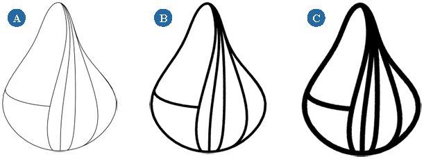
You can adjust the ink spread for individual objects that have a Toon Host shader (or Toon Paint and Host) applied to them. This scales the spread value defined by the Toon Ink Lens shader rather than replacing it. A value of 2, for example, doubles the current spread value, while a value of 0.5 halves it.
Basic ink line color is controlled by the Toon Ink Lens shader as part of the ink's basic appearance.
Select the camera that is rendering the ink lines and open its property editor (Modify Shader from the Render toolbar).
On the Lens Shaders tab, the lens shader stack appears. Select the Toon Ink Lens shader from the shader stack and click the Inspect button to open the shader's property editor.
From the Basic Appearance tab, adjust the Color values using the sliders.
You can also adjust the ink color for any Toon Host shaded object.
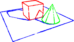
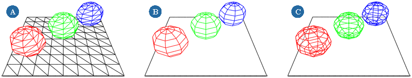
Here, all of the objects have the same ink line color, which is controlled by the Toon Ink Lens shader.
Each object has a Toon Paint and Host shader applied to it. The ink color override is active and each object has been assigned its own ink color, except for the grid whose ink color is still controlled by the Toon Ink Lens shader.
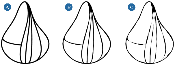
Tapering varies the spread of the ink lines based on specific criteria. You can Three types of tapering are available:
Anisotropy varies the spread at a specified angle. Typically, this is used to simulate a chisel-tipped pen.
Direction varies the spread so that ink lines are thickest where the object faces a specified direction and thinnest where it faces away.
For example, the default direction spread makes ink lines thickest where the objects faces the camera and thinnest where it faces away.
Distance varies the spread based on the object's distance from the camera. Typically, this is used to create depth fading.
| A |
No Tapering and Spread = 5 |
| B |
Anisotropy Tapering, Amount = 3, and Angle = 155 |
| C |
Direction Tapering, Amount = 1, and Vector = Camera |
| D |
Distance Tapering and Amount = 1 |
Select the camera that is rendering the ink lines and open its property editor (Modify Shader from the Render toolbar).
On the Lens Shaders tab, the lens shader stack appears. Select the Toon Ink Lens shader from the shader stack and click the Inspect button to open the shader's property editor.
From the Taper tab, activate Anisotropy tapering, if necessary, by setting the Amount to a non-zero value. The Amount value controls the strength of the effect.
Activate Direction tapering, if necessary, by setting the Amount to a non-zero value. The Amount value controls the strength of the effect. Adjust the following values to tune the direction-based taper.
Vector: Specifies the incident vector, relative to the object's surface, used to calculate the direction-based taper.
Space: Defines the coordinate space (World | Camera | Object) used for specifying the incident vector.
Direction Min/Max: Specifies the range of directions on which the effect is applied.
A value of 0 implies that the surface faces the incident vector (i.e., the surface normal is parallel to the incident vector).
A value of 90 implies a surface grazed by the incident vector (i.e., the surface normal is perpendicular to the incident vector).
Spread Min/Max: Defines the range of spread values to which surface directions are mapped. For example, a Min Spread of 2 would cause spread to increase by a factor of two at the specified Min Direction.
Profile Operation: Gives a nonlinear emphasis to the effect so that changes in spread may ease-in smoothly or cut in abruptly, for example.
Power: Controls the amount of emphasis created by the profile Operation.
Activate Distance tapering, if necessary, by setting the Amount to a non-zero value. The Amount value controls the strength of the effect. Adjust the following values to tune the distance-based taper.
In the case of secondary rays (those spawned as a result of reflection or transparency effects), the distance considered is that accumulated over the entire ray path, beginning at the camera and ending at the current ray-surface intersection.
Distance Min/Max: Specifies the range of distances to which the taper effect is applied.
Spread: Specifies the range of spread values to which distances are mapped. For example, a Min Spread of 2 would cause spread to increase by a factor of two at the specified Near Distance.
Profile Operation: Gives a non-linear emphasis to the effect, so that changes in spread may ease-in smoothly or cut in abruptly, for example.
Power: Controls the amount of emphasis created by the profile Operation.
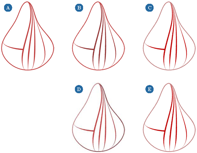
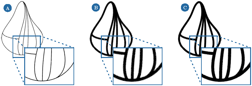
The width of hand-drawn contour lines tends to fluctuate a certain amount, depending on how steady the artist's hand is. You can simulate the irregularities inherent in hand drawing by using the variation options to create random variations in the ink spread.
| A |
No Variation, Frequency = 50,50,50, and Spread = 5 |
| B |
Variation = 0.5, Frequency = 50,50,50, and Spread = 5 |
| C |
Variation = 1, Frequency = 50,50,50, and Spread = 5 |
Select the camera that is rendering the ink lines and open its property editor (Modify Shader from the Render toolbar).
On the Lens Shaders tab, the lens shader stack appears. Select the Toon Ink Lens shader from the shader stack and click the Inspect button to open the shader's property editor.
From the Variation tab, activate the variation by setting the Amount to a non-zero value. Amount controls the strength of the variation.
Adjust the following parameters, as necessary:
Frequency (X, Y, Z): Defines the spatial frequency of the random variation. Higher values create noisier ink contours, while lower values create in more smoothly varying contours.
Animation: Controls the animation of the variation of the ink spread.
A setting of 0 disables the animation and freezes the variation over time.
Basis: Specifies the basis of the random variations. Each option creates a distinct effect.
Space: Specifies the coordinate space (World | Camera | Object) used for specifying the variation Basis.
Selecting camera coordinates computes variation relative to the camera. Camera coordinates might be appropriate for simulating hand-painted techniques.
Selecting world coordinates locks the effect to the direction of a surface regardless of its global orientation.
Selecting object coordinates rotates the effect along with the surface.
Variation: Specifies the range of input to which the effect is applied.
Spread: Specifies the range of spread values to which surface directions are mapped.
Profile Operation: Gives a non-linear emphasis to the effect, so that changes in spread may ease-in smoothly or cut in abruptly, for example.
Power: Controls the amount of emphasis created by the profile Operation.
The Pressure options simulate the pressure applied to a brush, pen, and so on, when drawing contours. The ink lines' color and alpha values are altered in proportion to the spread value.
Typically, this is used to create ink lines that fade as they become thinner, though you can create a variety of effects by experimenting with the values.
Select the camera that is rendering the ink lines and open its property editor (Modify Shader from the Render toolbar).
On the Lens Shaders tab, the lens shader stack appears. Select the Toon Ink Lens shader from the shader stack and click the Inspect button to open the shader's property editor.
From the Pressure tab, activate one or more pressure effects and adjust the following parameters:
Spread Min/Max: The range of spread values on which the effect acts. Each type of pressure has its own Min/Max values that correspond to a separate set of spread Min/Max values.
Brightness Min/Max: The range of brightness to which distances are mapped. A Min Brightness of 0.5 would cause ink to darken to half its original intensity at the specified Min Spread.
Saturation Min/Max: The range of saturation to which distances are mapped. A Min saturation of 0.5 would cause ink to fade to half its original saturation at the specified Min Spread.
Alpha Min/Max: The range of alpha to which distances are mapped. A Min alpha of 0.5 would cause ink to have half its original alpha value at the specified Min Spread.
If you want to add some complexity to the color of the ink lines, you can use textures to drive ink color. This can be done globally through the Toon Ink Lens shader or locally on objects that have a Toon Paint and Host or Toon Host shader applied to them.
To texture an individual object's ink lines, you have to drive its ink line color with a texture.
All of the objects' ink lines are controlled by the Toon Ink Lens shader.
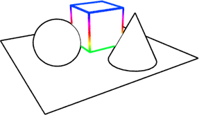
The ink color override is active in the cube's Toon Paint and Host shader, while a rainbow gradient is used to drive the override color parameter. To emphasize the effect, the cube's local ink spread was also increased.
Select the toon-shaded object whose ink lines you want to texture.
From the Render toolbar, choose Modify Shader to edit the object's Toon material shader. The Toon Paint and Host shader's property editor opens.
With the object still selected, open a render tree (press 7) and select a texture from the Nodes Texture menu.
Connect the texture to the host shader's host_override_color input.
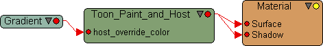
Double-click the texture's node to open its property editor and adjust the texture. Make sure to select an appropriate projection type for the object.
For more information about texture projection types, see Types of Texture Projection [ Texturing ].
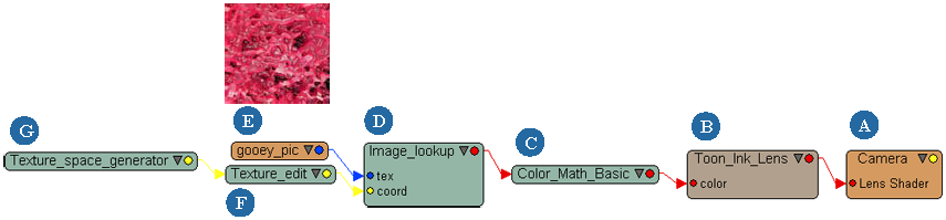
Texturing global ink lines is more complex than texturing a single object's ink lines because texture shaders do not generate texture coordinates for cameras. Instead, you have to use a series of shaders to generate these coordinates in order to control how the texture is applied.
The best approach is to use a Texture Space Generator shader to create the coordinates for a texture that you connect using either the Image Lookup shader or a Texture Generator shader. Connecting the texture's output to the Toon Ink Lens Shader's Color input renders the texture in the ink lines using the coordinates that you created.
The easiest way to do this is to open the camera's render tree and connect the shaders there. The following two examples demonstrate how to texture ink lines this way.
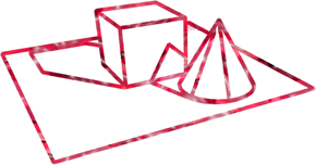
Driving the global ink line color with a texture means that every object's ink lines are colored by the texture, unless they have a local color defined by a Toon Host shader.
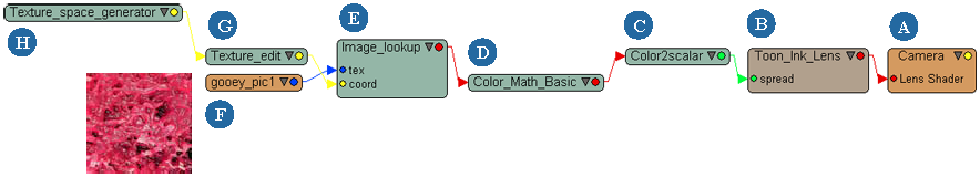
The last example demonstrated how to color global ink lines using a texture. You can use the same technique to alter global ink line spread.
By converting the texture into a scalar value and using it to drive the Toon Ink Lens shader's Spread parameter, you can create interesting variations in the ink lines' thickness.
When you alter the ink line spread globally, it does not affect individual objects' ink line colors. In this image the ink line color is controlled by each object's Toon Host shader, while the ink line spread is controlled globally by the Toon Ink Lens Shader.
You can specify where contours are detected based on boundaries between scene elements (between different objects or between objects and the background environment, for example) and based on Toon Host shader properties (like paint, shadows and transparency).
Select the camera that is rendering the ink lines and open its property editor (Modify Shader from the Render toolbar).
On the Lens Shaders tab, the lens shader stack appears. Select the Toon Ink Lens shader from the shader stack and click the Inspect button to open the shader's property editor.
From the Sampling tab of the Toon Ink Lens shader's property editor, select one or more of the following Boundaries options:
Environment: draws ink lines at the boundaries between object surfaces and the scene environment.
Object: draws ink lines where object surfaces intersect or overlap.
Material: draws ink lines at the boundaries between different materials.
Paint: draws ink lines that delineate the borders of paint regions on any toon shaded objects.
Shadow: wherever shadows are cast, ink lines are drawn between shadowed and unshadowed surfaces.
Transparency: draws ink lines at the boundary between transparent and opaque objects.
You can adjust the threshold of transparency/opacity using the Detection Threshold setting on Transparency tab of the object's Toon Paint and Host (or Toon Host) shader property editor.
If you want to render the scene objects' wireframes, set the Facet options. This is described in depth in the next section, Rendering Wireframes Using Facet Detection.
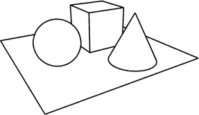
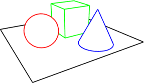
You can easily render the wireframes of some or all of your scene objects using the Toon Ink Lens shader's facet detection settings. When facet detection is enabled, contours are detected at the boundaries of an object's facets and rendered between all adjoining, intersecting, or overlapping triangles in the tessellated object surface.
In toon terms, this means that object wireframes are rendered as ink lines whose size, color, and overall look you can control as you see fit. Of course, you can further refine any object's wireframe by applying a Toon Material shader to the object and adjusting its local ink characteristics, making it transparent to expose the back-face of its wireframe, and so on.
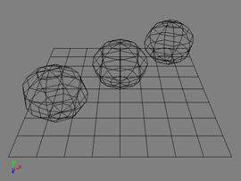
The images shown below are simple ink-only wireframe renders of the scene shown above. Ink line width is set to 2 and the basic ink color is set to black. However, each sphere has been given a different ink color. The background color is set to white.
Select the camera that is rendering the ink lines and open its property editor (Modify Shader from the Render toolbar).
On the Lens Shaders tab, the lens shader stack appears. Select the Toon Ink Lens shader from the shader stack and click the Inspect button to open the shader's property editor.
To make sure that only the ink lines are rendered, go to the Basic Appearance page and activate the Ink Only option.
You can also adjust the Color and Spread values to change the color and thickness of the ink lines respectively.
Now go to the Sampling tab and activate Facet detection. Select the Merge Coplanar option to hide the boundaries between coplanar triangles (see the previous illustration).
Follow the previous steps to render a wireframe. Lock the Toon Ink Lens property editor to keep it open (click the lock icon).
If the object does not have a Toon material applied to it, apply one now (Get Material Toon). The Toon Paint and Host property editor opens.
From the Toon Paint and Host property editor, click the Transparency tab and activate the transparency.
Set all of the transparency color values to 1 for full transparency.
From the Sampling tab of the Toon Ink Lens property editor, increase the Trace Depth value.
The trace depth determines how many levels of contour detection are computed. For example, to render a transparent object's front and back-face ink lines requires a trace depth value of 2 for two levels of contour detection.
Rendering the front-face ink lines of an object behind that transparent object requires an additional level, and so on. Keep in mind that increasing the trace depth can significantly increase render time.
The Seams options in the Toon Host shader allow you to hide ink lines where they would normally be rendered (blending) or create them where they normally wouldn't exist (unblending).
Blending ink lines allows you to hide ink lines in areas where they would normally appear. For example, areas where one object partially occludes another or where two objects intersect usually contain ink lines for both objects' boundaries. Blending can remove the ink lines from these areas.
For the ink lines to be hidden, one of the two overlapping objects must be a part of the other's blend objects list and within the specified occlusion distance. Alternatively, both objects can share the same blend group ID.
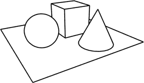
This ink-only rendering contains three overlapping objects (not counting the grid). The sphere and the cone partially occlude the cube, which creates ink lines.
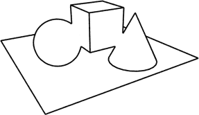
Making the sphere and the cone part of the cube's Blend group allows you to not render the ink lines that would ordinarily be created where the cube is occluded.
Select the toon-shaded object whose ink lines you want to blend with occluding/occluded objects.
From the Render toolbar, choose Modify Shader to edit the object's Toon material shader. The Toon Paint and Host shader's property editor opens.
From the Seams tab, click the Add button next to the Object list. From the pop-up explorer, select the object(s) whose ink lines you want to blend with those of the selected object. Click anywhere outside the explorer to close it and accept the selection.
Set the Group value to a non-zero value. This value becomes the object's blend group ID. Ink lines are hidden wherever the object overlaps another object with the same blend Group ID. You need to repeat this for any other objects whose ink lines you want to blend with the selected object's ink lines.
Set the Occlusion Distance value. This is a distance value measured in Softimage units. Surface samples from the occluding and occluded objects must be no farther apart than this distance for ink lines to be hidden.
Unblending ink lines is just the opposite of blending them: it creates ink lines where none would normally exist. Every Toon Host object has an unblend-group parameter that you can texture to create ink lines on the object, using the texture as their basis.
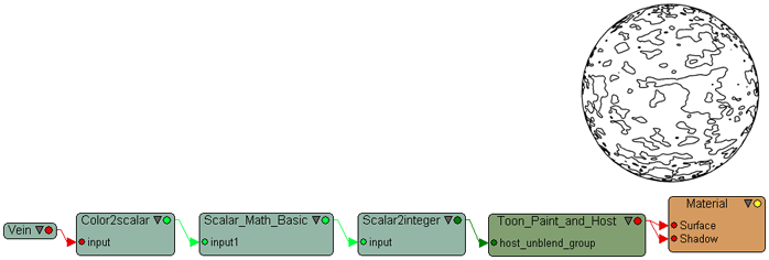
In this ink-only render, the host_unblend_group parameter was textured with a procedural vein texture, using the render tree shown below it. Adjusting the Scalar Math Basic shader's values determines which parts of the texture produce ink lines.
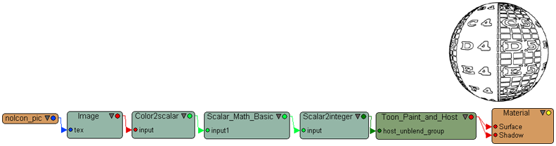
Another ink-only render. In this case, the host_unblend_group parameter was textured with the 2D no_icon.pic texture image using the render tree (as shown below it). Once again, adjusting the Scalar_Math_Basic shader's values determines which parts of the texture produces ink lines.
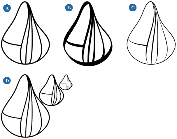
Sampling controls the quality of rendered ink lines to a large extent. The sampling value specifies the maximum number of rays fired to locate contours. The higher the sampling value, the higher the quality of the contours.
The default sampling value is 5, which is sufficient for rendering thinner contours (spread values less than 5 or 6). As contours get thicker (spread values of 7 and higher), however, they tend to become fuzzy at the edges and require higher sampling values.
All of these images were rendered with the following scene Antialiasing settings: Sampling Min/Max Level = 0/2 and Thresholds (RGBA) = 0.1, 0.1, 0.1, 0.1.
Select the camera that is rendering the ink lines and open its property editor (Modify Shader from the Render toolbar).
On the Lens Shaders tab, the lens shader stack appears. Select the Toon Ink Lens shader from the shader stack and click the Inspect button to open the shader's property editor.
From the property editor's Sampling tab, adjust the Samples value.
Because both the Toon Ink Lens shader's sampling setting and the render pass' antialiasing settings contribute to the quality of ink lines, it is important to balance them in order to optimize rendering.
For example, if you're rendering ink lines at the default spread value of 2, good values for a draft-quality render are:
Good values for a high quality render are:
As you make your ink lines thicker, you'll need to increase the Toon Ink Lens shader's Samples value, but you should not increase the antialiasing settings.
Instead, use the antialiasing settings to achieve the desired render quality whether or not the ink lines are rendered. Then adjust the Toon Ink Lens sampling to increase the quality of the ink lines.
For more information about antialiasing settings, see Controlling Aliasing [Rendering].
As you create Toon rendered scenes, you may want to preview the scene objects against a solid color background. This is especially useful when you're adjusting your ink lines.
Select the camera that is rendering the ink lines and open its property editor (Modify Shader from the Render toolbar).
On the Lens Shaders tab, the lens shader stack appears. Select the Toon Ink Lens shader from the shader stack and click the Inspect button to open the shader's property editor.
From the Background tab, enable the background and set the Color values.
You can render your toon-shaded scenes with two different types of lens distortion: fisheye and bulge.
Fisheye distortion simulates a hemispherical (fisheye) lens capable of rendering a 180-degree field of view with characteristic hemispherical distortion typical of real-world fisheye camera lenses.
Bulge distortion allows "bulging" of the lens by altering eye-ray direction. The lens may bulge out (convex, like a fisheye lens) or bulge in (concave). This effect may vary over the surface of the lens.
Select the camera that is rendering the ink lines and open its property editor (Modify Shader from the Render toolbar).
On the Lens Shaders tab, the lens shader stack appears. Select the Toon Ink Lens shader from the shader stack and click the Inspect button to open the shader's property editor.
From the Lens Effects tab, activate the type of distortion you wish to use — fisheye or bulge.
For either effect, adjust the Amount value. This controls the amount of distortion. A value of 0 negates the effect, while a value of 1 results in the full effect.
Do one of the following, depending on the type of distortion:
For fisheye distortion, adjust the Scale settings. This adjusts the proportions of the distorted image in X and Y. You can activate the Uniform option to force them to the same value.
For bulge distortion, adjust the Magnitude. The X and Y settings control the horizontal and vertical bulge respectively.
 Except where otherwise noted, this work is licensed under a Creative Commons Attribution-NonCommercial-ShareAlike 3.0 Unported License


