Displacement maps, though similar to bump maps, actually modify objects' rendered geometry according to an image map. This creates bumps, ridges, and other surface variations that cast shadows that correctly follow the displacement.
A displacement map is a scalar map that displaces a surface at each point in the direction of the object's normal: the geometry is distorted according to the map during the rendering process. Unlike regular bump mapping that "fakes" the look of real texture, the edges are visibly raised and can cast shadows that follow the displacement effect. Displacement affects the geometry of the object during the rendering process.
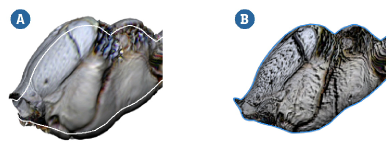
Displacement map (A) and bump map (B).
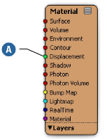
Open a render tree (press 7) and expand the object's Material node to reveal the Displacement port.
From the render tree's Nodes menu, select a Texture to use as a displacement map. Connect an image and select a texture projection as necessary — for more information see Applying a Texture.
Connect the output of the texture node to the input of the Displacement parameter of the Material node.
Even though the texture node's color output and the Displacement input's scalar input are not directly compatible, the render tree automatically inserts a Color2Scalar node to connect them.
Apply or edit a Geometry Approximation property as described in Applying and Editing Geometry Approximation [Scene Elements], and set options as desired on the Displacement tab.
In particular, set the Max Displ. setting to specify the maximum amount of displacement allowed on your object. A value of 0 disables the displacement while higher values limit the amount of displacement. It is critical that you set this parameter correctly because wherever an object's displacement exceeds this value, it will be clipped to this value (without creating a hole in the geometry). Make sure to set it high enough to accommodate the desired level of displacement.
For a complete description of all options, see Geometry Approximation Property Editor [Properties Reference].
Now that the displacement has been applied, you probably want to adjust its intensity. You can do this by choosing the Nodes  Image Processing Intensity shader.
Connect the Intensity shader between the texture shader that is creating the displacement and the Color2Scalar node.
Double-click the Intensity shader to open its property editor and adjust the Factor parameter to control the displacement on the object.
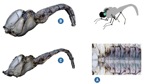
A displacement map on an object affects the rendered geometry (not the wireframe) of an object. Hence, creating a jagged displacement map (like the one shown previously) would cause jagged shadows of the texture. Displacement is controlled via the Intensity shader placed between the material node and the texture used to create displacement.
For moving objects with displacement, you can optimize the displacement approximation depending on how fast the object is moving by setting the Shutter Settings option on the Render Type tab of the mental ray Render Options Property Editor [Properties Reference]. The automatic reduction of displacement detail on moving objects has a significant impact on rendering performance and memory consumption by cutting down on the typically huge amount of tessellation data that gets generated.
The displaced geometry should have a geometry approximation property applied to it and motion blur must be enabled for the render region and/or the render pass. See Defining and Rendering Motion Blur [Cameras and Motion Blur].
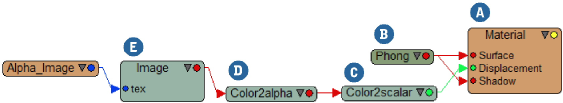
This section provides some examples of shader networks that you can build, in the render tree, to create displacement.
This example lets you use an image's alpha channel to create a displacement map on an object. You don't have to use the same texture to drive the diffuse or specular values of the object. In addition, the Alpha can be independently controlled with the Factor slider.
Although this example creates displacement, it is just as easy to create a bump map or use the alpha to define a texture.
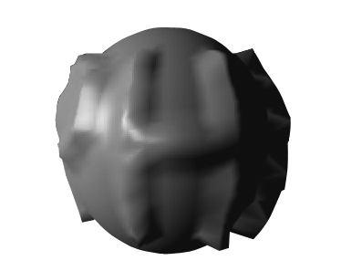
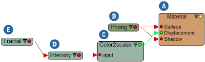
The material node's displacement input is the key to creating realistic displacement maps and animating them, too. This example uses a simple NURBS grid with a moderately high number of subdivisions.
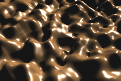
This chocolate-like surface was created using a simple Fractal procedural shader. Once the desired fractal values were obtained, an Intensity shader is used to control the overall displacement.
 Except where otherwise noted, this work is licensed under a Creative Commons Attribution-NonCommercial-ShareAlike 3.0 Unported License


