The texture support is a 3D object that defines the transformation and other basic characteristics of a texture projection. You can adjust the projection by manipulating the support object, and you can also modify the extent of the projection within the support.
Note that not every type of projection is associated to a support object. These procedures do not apply in those cases.
The position of a texture on an object is affected by the transformation of the support object. When the support moves relative to the textured object, the texture shifts on the textured object. You can transform a support directly, or constrain it to any object's bounding box.
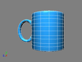
You can transform or constrain a texture support object in the same way as any other 3D object. For example, you can scale and translate a label into position on a package.
When you create a projection on a single object, the texture support is a child of the textured object. This means that by default the texture support moves with the object when you transform the object, and as a result the texture itself does not shift on the object.
Of course, you can cut the support from the object's hierarchy if desired for a specific effect. You can even animate the transformations of the support independently of the object.
For more information about transformations and constraints in general, see Transformations [Working in 3D Space] and Animating with Constraints [Animation].
By default, a texture projection fills the entire support. You can:
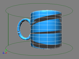
Change the extent of the projection on the support by transforming it interactively in the 3D views.
If you want to edit the UV coordinates of a projection after modifying it in either of these ways, you should freeze the projection or its transformation first.
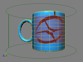
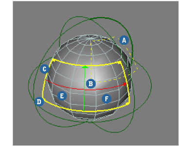
You can use the Edit Projection tool (J key) to scale, rotate, and translate a projection on a support.
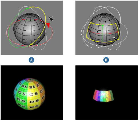
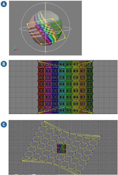
| A |
Selected texture support and unmodified projection (top) with the rendered result (bottom). |
| B |
Modified texture projection (top) with the rendered result (bottom). |
Choose Modify  Projection Edit Projection Tool from the Render toolbar or press J.
If the support has more than one projection associated to it, right-click to cycle through them. Alternatively, you can select the desired support in an explorer.
Click and drag on the projection manipulator as shown in the illustration below.
The SRT values are stored in the Texture Projection Definition Property Editor [Properties Reference]. If you prefer, you can set the values directly in the property editor, and even animate them.
When you have finished, exit the Edit Projection tool by pressing Esc or activating a different tool.
Rather than manually transforming a texture projection to fit over a specific area of an object, you can fit the texture projection to a selection of the object's components using the Fit Subcomponent UVs to Image tool. This tool automatically calculates and performs the necessary transformations to position the texture projection over the selected components. If necessary, you can then refine the projection's placement interactively in a 3D view or from the property editor, as described Transforming Projections on Supports in the 3D Views.
Select the components to which you want to fit the texture projection.
Then click Fit Subcomponent UVs to Image in the Texture Projection property editor.
If you did not select any components in step 2, you are prompted to pick them now. By default, the picking session uses the polygon filter and the raycast tool. but you can change the filter and tool if desired.
The texture projection is transformed to fit precisely over the selected components.
Once you have transformed a texture projection or fit it to a selection of components, you can "freeze" the transformation. Freezing the transformations bakes the transformation into the explicit UV coordinates but keeps the relation with the texture support object. In this respect, it is different from freezing the projection directly, which removes the support and collapses all texturing operators.
Before editing UV coordinates in the texture editor, you should freeze the projection's transformations or else you might not get the results you expect. You can then continue to manipulate the projection on the support, but don't forget to freeze the transformations again before you edit the UV coordinates again. Alternatively if you are certain that you no longer need to modify the texture support or change other options, you can freeze the projection completely (see Freezing Texture Projections).
When you freeze the projection's transformations, three things happen:
The projection's UV coordinates are modified to match the projection's transformation.
The ClsSetValuesOp operator is created in the texture operator stack (see The Texture Operator Stack).
The texture projection's UVW transformation values are reset to their defaults (scaling = 1,1,1; rotation = 0,0,0; translation = 0,0,0).
In the UVW transformation section, click Freeze.
The transformation is "frozen" into the object's UV coordinates and the UVW transformations reset to their default values.
There are two ways to revert the freezing of a projection's UVW transformations: you can either undo the freeze if that's still possible, or remove it entirely by deleting the ClsSetValuesOp operator. But note that deleting the operator means that you need to redefine the transformations from scratch.
 Except where otherwise noted, this work is licensed under a Creative Commons Attribution-NonCommercial-ShareAlike 3.0 Unported License