You can rotate individual particles to create many different effects, such as billowy smoke, flying debris, and swirling snowflakes.
You can set a particle's rotation (orientation) when it's emitted, which the particle keeps throughout its lifetime, unless some type of force makes it change. To add some variation to each particle's orientation, you can use a randomizing compound.
You can rotate the particles in different ways as they're emitted: align them to a surface, along their velocity, along a curve, or to a point to create billboard effects. You can also spin or roll them for different effects.
You can also find many rotation converters in the Rotation group on the Tool panel in the ICE Tree's preset manager.
One thing you may notice when particles collide with objects is that their rotation doesn't change after a collision. That is, if a rotated particle collides with an object, it doesn't change its rotation as might happen in real life (such as with faster rotation or changed rotational direction upon impact).
There are two particle attributes that are used to define particle orientation: Init_Orientation and Orientation. These attributes are used in several compounds, but you can also use them on their own in an ICE tree by specifying them in the Get Data and Set Data nodes, as described in Using ICE Particle Attributes.
For more information on attributes in general and a list of all available ICE attributes, see ICE Attributes.
You can determine the orientation in which the particles are emitted from the emitter object. Their orientation stays the same over their lifetime.
Create a particle emission — see Setting Up Any Type of ICE Particle Emission.
In the Emit compound's property editor, set either of these:
Select the Align to Surface Normal option to align the particle's Y axis along the normal of the emitter object.
Set the Orientation of the particle on its local X, Y, and/or Z axes. You can choose which of its axes any combination of them) around which the particle rotates. Like the classic airplane analogy:
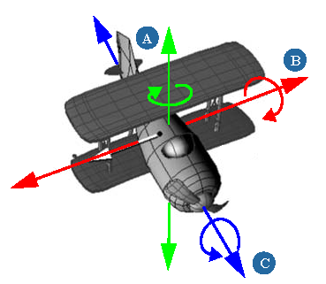
Then enter a specific Angle value, which is the amount of rotation in degrees around that axis.
For example, if the axis is (X=0, Y=0, Z=1) and the angle is 45, this means that the particle is rotated around its Z axis by 45 degrees. The angle specifies the amount of rotation, while the vector is the particle's axis around which it is rotated.
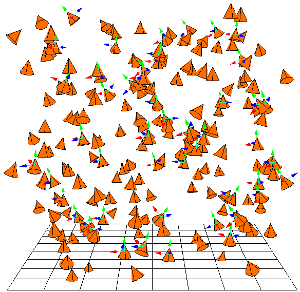
To help you visualize the orientation of each particle, change the display shape for the particles to a Cone in the Particle Display property editor. With a cone, you can see in which direction the particles are pointing, which is especially when you're modifying their orientation with compounds.
You can also create a display attribute using the particle's Orientation, then choose to display this as axes, angle numbers, angles, or a numeric value. This is especially useful if you're working with wireframes or bounding boxes of particles, such as for instanced geometry.
For information, see Creating Particle Display Attributes.
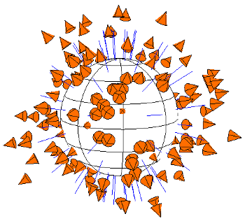
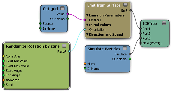
You can randomize the initial orientation in which the particles are emitted using the Randomize Rotation by Cone compound. This compound lets you define the range of angle values that are randomly applied to the particles so that they are emitted using different rotation values. The particles' orientation stays the same over their lifetime.
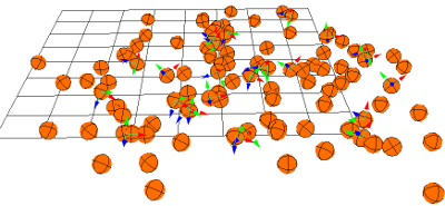
Particles are randomly rotated around their Y axes upon emission using values between 0 - 45 degrees and a twist.
Create a particle emission — see Setting Up Any Type of ICE Particle Emission.
In the ICE tree's preset manager, click the Task tab and select Particles.
Drag the Randomize Rotation by Cone compound from the Modifiers group into the ICE view.
Plug this compound's Result output into any Orientation port, such as the one in the Emit compound.
In the Randomize Rotation by Cone property editor, set the Cone Axis, which is particles's local axis along which the randomization of the rotation occurs.
Then set the Start and End angle values, which creates the angle range in which the particle rotation can vary (0 - 360 is full rotation range).
You can also set a Twist value range, which is how much the particles rotate around their Y axis.
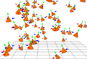
The Roll Particles compound rotates (rolls) particles at a rate relative to their size. You can set the particle's up vector value to define an axis along which it rolls, which is useful for creating effects such as rolling marbles or tumbling rocks.
If you want define a surface upon which the particles can roll, you can use the Slide on Surface compound, which contains the Roll Particles compound (see ICE Particles Sliding on Obstacles).
Particles rolling on the XZ plane.
Create a particle emission — see Creating a Basic Particle Emission.
Choose the Particles  After Emission Roll Particles command from the ICE toolbar.
This command adds the Roll Particle compound to the ICE tree, plugging it into the Execute port of the Simulation Root compound.
In the Roll Particle property editor, set the values.
The Spin Particle compound appropriately spins particles around an axis at a certain number of revolutions per second. This is useful for creating effects such as billowing smoke and explosions.
You can use this compound in conjunction with other orientation compounds. For example, use the Align on Velocity compound to set the forward direction to X=1, then you can spin the particle using that axis as well to create a bullet spiralling effect.
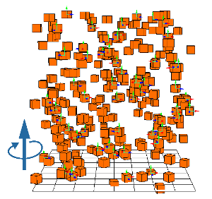
Particles spinning around their Y axes at a rate of 1 revolution per second as they're emitted.
Create a particle emission — see Creating a Basic Particle Emission.
Choose the Particles After Emission Spin Particles command from the ICE toolbar.
This command adds the Spin Particle compound to the ICE tree, plugging it into the Execute port of the Simulation Root compound.
In the Spin Particle property editor, set the Spin Axis, which is the axis around which the particle spins, and the Spin Rate, which is the number of times the particle revolves per second.
The Align on Velocity compound orients a particle to point along its direction of movement (vector). This is useful for creating effects such as flocks of birds, arrows, crowds, trajectories, bullets, or anything that needs a specific orientation relative to its movement.
If you're using the Flow Along Curve compound, this compound is built in as an option — see ICE Particles Flowing Along a Curve for more information.
Create a particle emission — see Creating a Basic Particle Emission.
Choose the Particles After Emission Align on Velocity command from the ICE toolbar.
This command adds the Align on Velocity compound to the ICE tree, plugging it into the Execute port of the Simulation Root compound.
In the Align on Velocity property editor, set the Local Vector, which is the axis that is used to align the particle, and the Weight, which defines how much the particle is rotated each frame. You can also set a maximum value to limit the amount of rotation.
There are three compounds that let you do billboarding effects: Align Particle to Camera, Billboard Orientation, and Align Particle to Position.
The Align Particle to Camera compound aligns particles to the global position of a camera root so that particles' Y axes are pointing toward the camera, allowing you to do "billboard" effects.
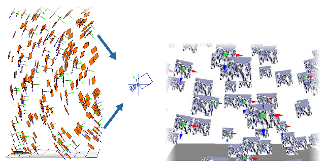
On the left, particle billboards change their orientation so that their Y axes are always pointing toward the camera root.
On the right, the Camera's viewpoint of the textured particle billboards that are facing it.
Create a particle emission — see Creating a Basic Particle Emission.
Choose the Particles After Emission Align to Camera command from the ICE toolbar.
This command adds the Align Particle to Camera compound to the ICE tree, plugging it into the Execute port of the Simulation Root compound.
In the Align Particle to Camera property editor, specify the name of the camera's root: either click the Pick button and pick a camera root in the scene, or click the Explorer button and select a camera root name from the list, or enter a camera root's name in the text box.
In the same property editor, select the Alignment Method for the particles.
You can also use the Align Particle to Position compound aligns particles to any position in global space, including any object's global position.
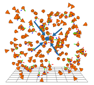
Particles change their orientation so that their Y axes are always pointing at a position in global space. You can also use an object's global position to have particles always face that object.
The Align Particles to Vector assigns a particle vector to point along a different vector. For example, you can assign the particle's Y axis to point along the X vector or along a specific vector from an object or one that you've defined.
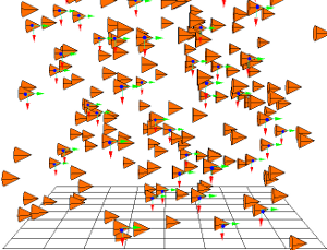
Particles have their Y axis assigned aligned to point along the X vector.
Create a particle emission — see Setting Up Any Type of ICE Particle Emission.
In the ICE tree's preset manager, click the Task tab and select Particles.
Drag the Align Particle to Vector compound from the Orientation group into the ICE view.
Plug this compound's Execute output into a Port on the ICETree node.
Open the property editor for Align Particles to Vector and select the Local Vector that is used to align the particles. The Y axis is typically the vector that points along the length of a particle. If you change your particle shape to a cone, you can see that the Y axis is the direction of the cone point. The X and Y axes are the sideways axes.
If you want to use an object or a specific vector, plug its Vector output into the To Vector port of the Align Particles to Vector compound.
If you're not using an input object, select the To Vector value which is the vector along which you want the Local Vector to point.
Set the Weight, which defines how much the particle is rotated each frame. The value is a ratio, so if you set it to 1.0, the particle is immediately aligned. If you set this value to 0.1, the particle rotates by 10% each frame.
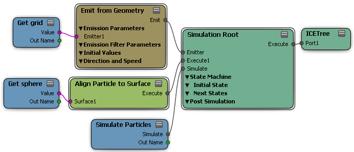
The Align Particles to Surface compound makes particles point along the direction of the normals of a surface object. This is useful for setting up anything that needs a specific orientation along an object, such as bugs crawling on a rock or something sliding over a surface.
If you're using the Flow Around Surface compound, this compound is built in as an option — see ICE Particles Flowing Around an Object for more information.
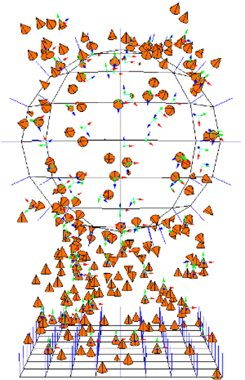
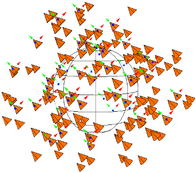
Particles change their orientation so that their Y axes are in the direction of an input object's (sphere's) surface normals when they're within a certain distance of it.
Create one or more polygon mesh objects to which you want to align the particles. For example, you can have the particles move between objects and align with each one when they are within a certain distance.
Create a particle emission — see Creating a Basic Particle Emission.
Choose the Particles Collision Align to Surface command from the ICE toolbar.
This command adds the Align Particle to Surface compound to the ICE tree, plugging it into the Execute port of the Simulation Root compound.
Pick one or more objects to use for the particle alignment. Each object's Get data node is then plugged into the Surface port of the Align Particle to Surface compound.
You can also add more objects to the ICE tree later — drag each obstacle's name into the ICE Tree view to create a Get Data node for it, then plug it in as the other objects.
In the Align Particle to Surface property editor, set the parameters as you like for the alignment. This affects the interaction of the particles with all objects that are plugged into this compound.
 Except where otherwise noted, this work is licensed under a Creative Commons Attribution-NonCommercial-ShareAlike 3.0 Unported License