The simplest way to create a particle emission is to use the Basic Emission command. When you emit particles using this command, a set of points called a point cloud is created and emitted from the object you select to be the emitter. Each point cloud has its own ICE tree associated with it. You can have any number of point clouds in a scene, each having one or more ICE tree.
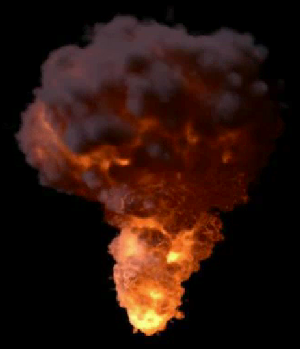
Particles are emitted from a bomb as it explodes.
Select one or more objects to be particle emitters.
An emitter can be any type of object that has geometry: a polygon mesh, NURBS surface, a curve, or a combination of these object types.
Choose the Particles  Create Basic Emission command from the ICE toolbar.
When you do this, the following things happen:
A point cloud is created. You can give this a new name, if you like.
An ICE tree for that point cloud is created in the ICE Tree view. The necessary nodes that are used to emit particles from the selected emitter object are already connected in the ICE tree — see below.
The Emit from Geometry property editor opens in which you can set the particle attributes — see below for more information.
Click the play button in the playback controls below the timeline to see the particles being emitted.
Particles are emitted starting at the second frame of the simulation frame range. For example, if the start frame of the simulation is set to 1, the simulation starts then, but particles are not actually emitted until frame 2.
This is because the initial state of the particle emission is set at the first frame of the simulation range — see Creating an Initial State for ICE Particle Simulations.
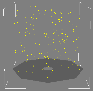
By default, the particles are small yellow points, but you can change all that. You'll also notice a bounding box around the particles to indicate that the point cloud is selected.
With the point cloud selected, open the ICE tree by pressing Alt+9.
You may need to click the Refresh icon on the toolbar to update the ICE tree view.
As you can see, there are nodes already connected for you. These nodes are the ones that you usually need as a base for particle emissions.
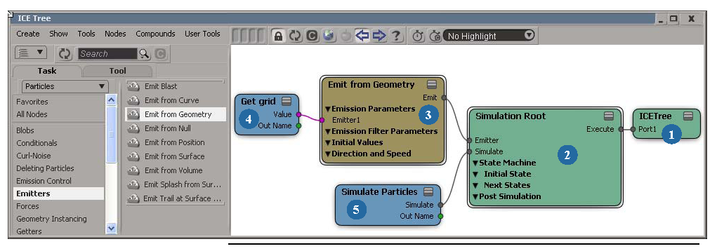
| 1 |
The ICETree node is the main node in any ICE tree. Because this is a particle simulation, the ICETree node is simulated. At each frame, the ICETree node processes all nodes and compounds that are connected to its ports, from top to bottom. See ICE Simulation Regions and Nodes for more information. |
| 2 |
The Simulation Root node is "central station" for ICE simulation nodes. It needs to be plugged into the ICETree node. This node gives you easy access to many ports in which you can plug in nodes that are often used in simulations. In this case, the Emit from Geometry and Simulate Particles nodes are plugged into it. To use the commands on the ICE toolbar, you need to have this node plugged into the point cloud's ICE tree. NoteThere are two versions of this node: a simple one (version 1.0) and one that includes the State Machine ports (version 2.0).
See Simulation Root for more information.
|
| 3 |
The Emit from Geometry compound is responsible for creating and emitting the particles. At every frame, it adds points and sets their attributes such as size, color, velocity, mass, shape, etc. You can open the Emit compound's property editor and change all these attributes as you like. Emit compounds are usually plugged into the top of the Simulation Root node in a particle simulation because you need to emit the particles before anything else can happen to them. See Setting Up Any Type of ICE Particle Emission for information on other Emit compounds you can use. |
| 4 |
A Get Data node represents the particle emitter object in the ICE tree and gets data from it so that it can be used in the ICE tree. In this case, the node is called Get grid because that's the name of the emitter object. |
| 5 |
The Simulate Particles node updates the position and velocity of each particle at each frame based on its mass, position, and velocity (based on the forces affecting them) of the previous frame. Updating each frame based on the previous frame is what makes the particles simulated. The Simulate Particles node takes all information from the compounds that are plugged in above it and then uses that information to update each particle at each frame. See The Simulate Particles and Simulate Rigid Bodies Nodes for more information. |
If want to quickly open certain compound or node property editors for the selected point cloud, you can use these two commands. These commands can be handy if the ICE tree isn't open, but you want to make some adjustments:
Choose the Particles Simulation Inspect Emitter command from the ICE toolbar to open up the selected point cloud's Emit compound property editor.
Choose the Particles Simulation Inspect Simulation Root command from the ICE toolbar to open up the selected point cloud's Simulation Root compound property editor.
Choose the Particles Simulation Inspect Simulation Node command from the ICE toolbar to open up the selected point cloud's Simulate Particles or The Simulate Rigid Bodies Node node property editor.
 Except where otherwise noted, this work is licensed under a Creative Commons Attribution-NonCommercial-ShareAlike 3.0 Unported License


