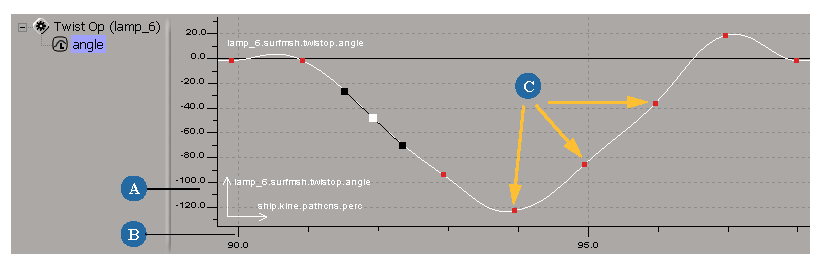
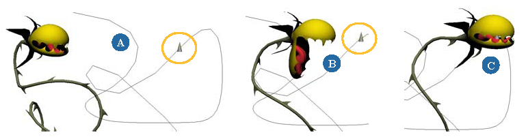
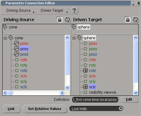
When you link one or more parameters to a single driving parameter, you specify that each linked parameter's value is to be controlled (driven) by the animation of the driving parameter. For example, you can have a venus flytrap plant automatically open its mouth when a path-animated "fly" is at a certain distance from it.
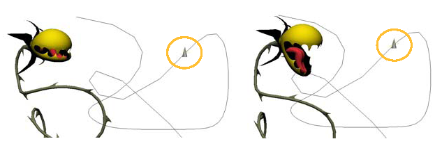
Venus flytrap eyes its victim. Its jaw's rotation Z parameter is linked to (driven by) the position X parameter of the fly that is animated along a path.
Linked parameters provide you with a quick and easy way to create relationships between parameters without having to work out the mathematical expressions involved. They are especially useful with custom parameters, such as when you create a custom control panel with sliders to control a rig (see Custom and Proxy Parameters).
Linked parameters are similar to expressions (in fact they create a special type of expression: l_fcv), but the value of driving parameter controls the linked parameter as dictated by a function curve rather than by a mathematical formula (see Editing Linked Parameter Fcurves).
While you usually only link one parameter to one driving parameter, you can link several parameters to the same driving parameter. You can also create multiple sets of "one-to-one" links at the same time. No matter how you create the links, an l_fcv expression is created for each linked parameter. As well, when a parameter is linked, its animation icon displays an "L" to indicate this state.

To link one or more parameters to a single driving parameter
Do one of the following to open the parameter connection editor:
Choose View  Animation Parameter Connection Editor from the main menu.
You can also first select an object whose parameters you want to be linked to (driven by) another parameter and then open this editor.
In a property editor or explorer, right-click the animation icon of the parameter you want driven by another and choose Link With.
Choose Link With or Parameter Connection Editor from the Animation menu on the Animation panel.
Then follow the steps outlined in this overview:
| 1 |
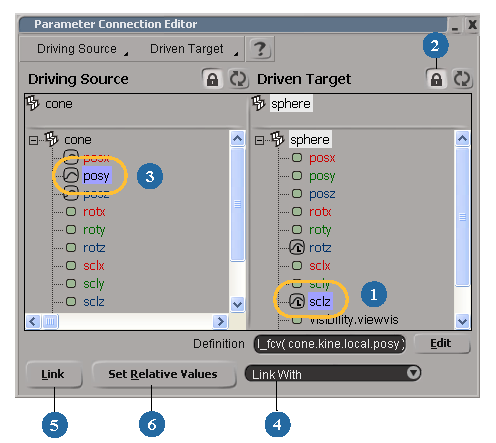
Select an object, then select one or more of its parameters in the Driven Target explorer. These are the parameters whose values will be controlled by the driving parameter. |
| 2 |
Click the lock icon to prevent the explorer from changing when you select other objects. |
| 3 |
Select an object, then select one of its parameter in the Driving Source explorer. This is the parameter whose values will control the linked parameters. |
| 4 |
Select Link With from the link list. |
| 5 |
Click the Link button. A link relationship is established between the parameters. An l_fcv expression appears in the Definition text box and the animation icon of the linked parameter displays an "L" to indicate this.
|
| 6 |
Set the driving and linked parameters' values as you want them to be relative to each other, then click the Set Relative Values button. See Setting Relative Values below for more information. Repeat this step for each relative state you want to set. |
Creating Multiple Sets of Linked Parameters
In addition to linking multiple parameters to one driving parameter, you can create multiple sets of linked parameters at the same time. The important thing to know for doing this is that you need to have the same number of linked and driving parameters, and the order in which you select the parameters determines what's linked to what.
For example, if you select SclX, SclY, SclZ parameters in this order in the Driven Target explorer, then select the Posx, Posy, Posz parameters in that order in the Driving Source explorer, a linked parameter is created for each set (PosX drives SclX, PosY drives SclY, etc.).
To create multiple sets of linked parameters at the same time
Select any number of parameters in the Driven Target explorer.
Using the same number of parameters, select the parameters in the Driving Source explorer in the order you want to match up with the selected linked parameters.
A link relationship is established between each matching set of linked and driving parameters. An l_fcv expression appears in the Definition text box and the animation icon of each linked parameter displays an L to indicate this.
Relative values are "keys" that map a particular value of the driving parameter to a particular value of the linked parameter. They are similar to regular keys that map a particular value to a particular frame. However, instead of the values being mapped over time, the linked parameter's values are mapped in relation to the driving parameter's values.
Set a value for the driving parameter as you want it to be relative to the linked parameter.
Set a value for the linked parameter as you want it to be relative to the current state of the driving parameter.

Do one of the following to set the relative values of these parameters:
Click the Set Relative Values button in the parameter connection editor.
In a property editor or explorer, right-click the animation icon of the linked parameter and choose Set Relative Values.
Select the object with the linked parameter and choose Set Relative Values from the Animation menu on the Animation panel.
Repeat these steps for as many relative states as you want to set.
When you set the relative values, a link fcurve is created that represents the relationship between the linked and driving parameters. You can edit the link fcurve in the animation editor, as described in the next section.
Editing Linked Parameter Fcurves
When you set the relative values for linked parameters, a link fcurve is created that represents the relationship between the two parameters. Instead of the values being mapped over time, as is the case with typical fcurves, the linked parameter's values are mapped in relation to the driving parameter's values. Each key on the fcurve represents a relative value that you have set.
To change the function curve interpolation to linear
Like most function curves, the link curve's interpolation is spline by default, but you may want to change it to linear to prevent having an ease-in and ease-out for the curve (most fcurves should be at a constant speed).
Select the function curve and click the Linear Interpolation icon or choose Curves Linear Interpolation in the animation editor's toolbar.

For information about editing function curves in general, see Editing Function Curves.
Example: Linking the Opening Doors to a Missile
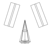
This is a simple example showing you how to link parameters from two different objects to one animated parameter. You will link the opening of an underground launch pad's silo doors (rotation Z parameters) to the position of the missile (position in Y) taking off from below.
|
|
|
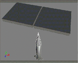
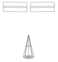
Create the silo doors and the missile using primitives
Working in the Front viewport, create the missile doors by getting two cubes and scaling them so they're flat.
Get a cone to represent the head of a missile. Position the missile where you want it to be before the doors start opening.
At frame 1, set a key for the missile's current position (translation) in Y.
Link each door's rotation with the missile's position
You want the opening of the doors to be affected by the missile's location. To do this, you will link the doors' rotation on Z with the missile's position in Y.
Select both doors and open the parameter connection editor. The door objects are displayed at the top of the Driven Target explorer.
Select the RotY parameter for each door (Ctrl+click) in the lower part of the Driven Target explorer.
Click the lock icon for this explorer to prevent it from changing when you select another object.
Select the missile object in a viewport so that it appears at the top of the Driving Source explorer.
Select the PosY parameter in the Driving Source explorer.
Click the lock icon for this explorer to prevent it from updating.
Select Link With from the link list at the bottom of the parameter connection editor.
Each door's RotZ parameter is now linked to the missile's PosY parameter. An l_fcv expression is created for each linked parameter and displayed in the Definition text box. The animation icon of each linked parameter displays an "L" to indicate this.
Now that the link between each door's Z rotation and the missile's Y translation has been established, you must define the relative values between these parameters.
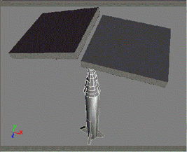
Translate the missile along the Y axis to where you want the door to start opening.
Click the Set Relative Values button in the parameter connection editor.
Go to another frame in the timeline (such as frame 50) and translate the missile along the Y axis to where you want the door to be completely open. Set a key for this value.
Rotate each door in Z to create the widest open position.
Click Set Relative Values again.
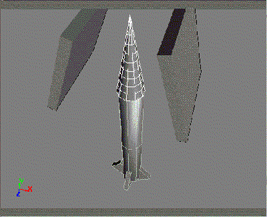
Et voilˆ! When you play back the animation, notice how the doors automatically open as the missile moves up in preparation for its launch into space!