Softimage has tools and commands that let you draw and manipulate curves in a variety of ways.
Things You Should Know About Drawing and Manipulating Curves
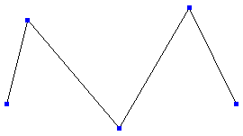
In Softimage, you can draw and manipulate two types of curve: linear and cubic. Linear curves are composed of straight segments, and cubic curves are composed of curved segments.
|
|
| Linear Curve |
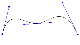
Cubic Curve Knot has multiplicity 1. |
|
|
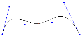
| Cubic Curve Knot has multiplicity 2. |
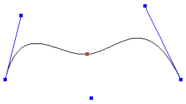
Cubic Curve Knot has multiplicity 3 (Bézier). |
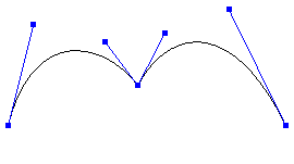
On a cubic curve, each knot can have a multiplicity of 1, 2, or 3. This value refers to the number of control points associated to the knot. In general, knots with higher multiplicity are less smooth but provide more control over the trace of the curve. A knot with multiplicity 3 is like a Bézier point, with one control point at the position of the knot and the other two control points acting as the tangent handles.
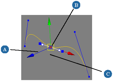
The Tweak Curve tool allows you to manipulate these knots in a Bézier-like manner — see Using the Tweak Curve Tool. Whether the back and forward tangents remain aligned depends on how you manipulate them — it is not a property of the knot itself.
|
|
| Broken tangents create a sharp corner. |
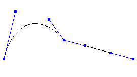
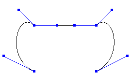
Four control points create a straight segment when they are lined up. |
Bézier knots also allow you to create straight segments by rotating the tangents to point at adjacent knots, so that four control points are lined up in a row. Again, whether the control points remain lined up depends on how you manipulate the adjacent knots — it is not a property of the segment. See Drawing a Combination of Linear and Curved Segments.
There are several ways to draw curves:
By placing control points, knots, or Bézier knots explicitly. See Drawing Curves by Placing Control Points or Knots.
By holding the mouse button down and dragging continuously, as if you were sketching with a pen. This method creates cubic curves only. See Sketching Curves.
Drawing Curves by Placing Control Points or Knots
You can draw cubic or linear curves by clicking to place control points or to place knots. Use one of the following commands
from the Create Curve menu of the Model or Animate toolbar:
Draw Cubic by CVs allows you to place control points (also known as control vertices or CVs). The curve does not pass through the locations you click but is a weighted interpolation between the control points. As you add more points, the existing knot positions may change but the point positions do not.
Draw Cubic by Bézier-Knot Points allows you to place knots of multiplicity 3. The curve passes through the points you click. As you add more knots, the positions of the control points are automatically adjusted to ensure maximum smoothness of the curve as the curve passes through the existing knot positions.
Draw Cubic by Knot Points allows you to place knots of multiplicity 1. Again, the curve always passes through the locations you click and the positions of the control points are automatically adjusted as you add more knots.
Draw Linear allows you to draw lines of connected straight segments (sometimes called polylines). The straight segments meet at the locations you click.
The choice between linear, cubic Bézier, and cubic non-Bézier drawing tools depends on the situation. When creating profiles for modeling, linear curves give a good sense of the final result. For paths, you'll want cubic curves — non-Bézier curves are smoother but you may find Bézier curves easier to control. Bézier curves also give you the ability to have sharp corners, and to mix curved and straight segments. The choice between placing control points or placing knots to draw cubic non-Bézier curves is simply a matter of personal preference.
When drawing curves, snapping can be very useful for controlling the position of points and knots. For more information, see Snapping.
You can also activate symmetry when drawing curves; see Drawing Curves Symmetrically.
To draw a curve by placing control points or knots
Choose the appropriate command from the Create Curve menu on the Model or Animate toolbar:
Click in any geometry view to add the first point, and continue clicking to add more points. Before you release the mouse button, you can drag the mouse to adjust the point's location.
To add a point at the end of the curve, use the left mouse button.
To add a point between two existing points, use the middle mouse button.
To add a point before the first point, first right-click and choose LMB = Add at Start and then use the left mouse button. To return to adding points at the end of the curve, first right-click and choose LMB = Add at End.
Other useful commands are available on the context menu when you right-click: Open/Close (see Opening and Closing Curves), Invert (see Inverting Curves), Start New Curve, and, of course, Exit Tool.
When you have finished drawing, exit the curve drawing tool by choosing another tool, pressing Esc, or right-clicking and choosing Exit Tool.
Alternatively, if you want to draw another curve right away, middle-click Create Curve on the toolbar or right-click and choose Start New Curve.
You may be surprised that a cubic curve is drawn after the second point, even though it takes four points to define a cubic curve segment. This is because points are automatically being created so that there are always at least four.
When you click to place the first point, four points are added at the same location.
When you click to place the second point, the three extra points at the first location are removed and three are added at the second location so that the total remains equal to four.
When you place the third point, the two extra points at the second location are removed and two more are added at the third location.
Drawing a Combination of Linear and Curved Segments
Although Softimage does not support having linear and cubic NURBS segments in the same subcurve, you can use Bézier knots to obtain straight segments on a cubic curve:
If you have already begun drawing a linear curve, raise its degree (see Raising the Degree of Curves) then use Modify Curve Add Point Tool by Bezier-Knot Points to draw curved sections (see Adding Points and Knots on Curves Interactively). Press Shift while adding knots to preserve the existing trace if you want the last-drawn segment to remain straight.
If you have already begun drawing a cubic curve, place the knots where you want them and then straighten the desired segments as described in Creating Straight Segments.
Straight segments are not inherently linear. Whether they remain straight depends on how you manipulate them. Using the Tweak Curve tool to move the knot preserves the linearity, but it will break if you move a tangent or use another tool.
When drawing curves, you can activate symmetry. This automatically creates a second curve object that mirrors the one you draw across the current symmetry plane.
Note that symmetry does not work when sketching curves, nor when adding points to existing curves.
Sketching allows you to draw a cubic curve by dragging the mouse freehand as if it were a pen. It creates a cubic curve with knots of multiplicity 1.
Choose Create Curve Sketch on the Model or Animate toolbar. The mouse pointer changes to a pen.
Release the mouse button to create the curve. The sketch tool remains active and you can continue to draw more curves.
Curve Fit on Curve to resample a sketched curve. For more information, see Fitting Curves onto Curves.
Adding and Deleting Components on Curves
There are several ways to add and delete control points and knots on curves:
You can add control points, knots, or Bézier knots interactively. This allows you to control the placement simply by clicking. See Adding Points and Knots on Curves Interactively.
You can delete control points interactively or manually. See Deleting Control Points on Curves.
You can add and delete knots manually. See Adding and Deleting Knots Manually.
You can set the multiplicity of knots on cubic curves. See Setting Knot Multiplicity.
Adding Points and Knots on Curves Interactively
The procedure for adding control points and knots interactively to an existing curve is similar to drawing a new curve from
scratch, but uses tools on the Modify Curve menu of the Model toolbar instead of Create Curve.
When adding points or knots, snapping can be very useful for controlling the position of points. For more information, see Snapping.
To add control points or knots
Choose the appropriate command from the Modify Curve menu on the Model or Animate toolbar:
For cubic curves, Add-Point Tool by CVs lets you place control points (also known as control vertices or CVs). The curve does not pass through the points you click but is a weighted interpolation between the points. As you add points, the existing knot positions may change but the point positions do not.
For cubic curves, Add-Point Tool by Bezier-Knot Points lets you place knots. The curve always passes through the locations you click. As you add knots, the positions of the control points are automatically adjusted.
For cubic curves, Add-Point Tool by Knot Points lets you place knots. The curve always passes through the locations you click. As you add knots, the positions of the control points are automatically adjusted.
For linear curves, knots and control points are coincident so the three commands are all equivalent.
Click in any geometry view to add points. Before you release the mouse button, you can drag the mouse to adjust the point's location.
To add a point at the end of the curve, use the left mouse button.
To add a between two existing points, use the middle mouse button.
To add a point before the first point, first right-click and choose LMB = Add at Start and then use the left mouse button. To return to adding points at the end of the curve, first right-click and choose LMB = Add at End.
Other useful commands are available on the context menu when you right-click: Open/Close (see Opening and Closing Curves), Invert (see Inverting Curves), Start New Curve, and, of course, Exit Tool.
When you have finished, exit the tool by choosing another tool, pressing Esc, or right-clicking and choosing Exit Tool.
Deleting Control Points on Curves
You can delete control points on curves manually using the Delete key or interactively using the Delete Point tool.
Adding and Deleting Knots Manually
You can add or remove knots on a curve manually. The control points are automatically adjusted.
To manually add knot of multiplicity 1 to a curve
A knot of multiplicity 1 is added to the curve and an Insert Crv Knot operator is added to the construction history. If you want to adjust the multiplicity, you can either open the Insert Crv Knot Op property editor or follow the procedure described in Setting Knot Multiplicity.
Select one or more knots on a curve, and choose Modify Curve Remove Knots.
Select one or more knots on a curve, right-click on a selected knot, and choose Remove Knots.
While the Tweak Curve tool is active (see Using the Tweak Curve Tool), right-click over an individual knot and choose Remove Knot.
The selected knots are removed, and a Remove Crv Knot operator is added to the construction history.
You can change the multiplicity of a knot to suit your needs. For example, reducing the multiplicity makes a curve smoother, but increasing the multiplicity to 3 allows you to use Bézier controls and make sharp angles. Changing the multiplicity of knots can alter the trace of a curve in some circumstances.
To set the multiplicity of a knot
Select one or more knots on a cubic curve. To affect all knots on one or more curves, select the curve objects instead.
Choose one of the following commands from the Modify Curve menu of the Model toolbar:
Make Knots Bezier set the multiplicity of the selected knots to 3.
Make Knots Non-Bezier set the multiplicity of the selected knots to 1.
Set Knots Multiplicity opens the Set Crv Knot Multiplicity Op property editor, where you can set the multiplicity of the selected knots to 0, 1, 2, or 3. Setting it to 0 is equivalent to removing the knot.
The main tool for manipulating curve components is Tweak Curve, although you can also use other tools if desired.
The Tweak Curve tool allows you to manipulate curves in a Bézier-like manner. In addition to Bézier knots, you can manipulate non-Bézier knots, control points, and isopoints. The Tweak Curve tool also supports snapping — see Snapping.
Activate the Tweak Curve tool by pressing M or choosing Modify Curve Tweak Curve from the Model toolbar.
A manipulation handle appears (by default, on either the first knot or the last selected knot).
Note that pressing M when a curve is not selected will activate the Tweak Component tool instead.
As you move the mouse pointer close to a knot, the manipulator jumps to it. Do any of the following:
Click and drag the manipulator's handles to adjust the knot's position, tangent angle, or tangent length. See To use the Tweak Curve manipulator.
Click and drag a control point to move it to a new location.
Select an isopoint by clicking on a curve segment between knots. A manipulator appears at the isopoint — see To use the Tweak Curve manipulator. To select an isopoint that is very close to a knot, you can click on the curve farther away and then slide the mouse pointer closer before releasing the button.
Right-click on a knot or isopoint manipulator to access a context menu containing commands that affect that point, as well as other tool options.
Note that if you right-click on a selected knot (or on another part of the curve while knots are selected), the context menu is different (although many of the same items are available on both menus). In this case, the commands apply to all selected knots and not just the one under the mouse pointer.
Click and drag a rectangle across one or more knots to select them. Use Shift to add to the selection, Ctrl to toggle, or
Ctrl+Shift to deselect. This allows you to apply commands to multiple selected knots using the context menu or the Modify Curve menu.
The Tweak Curve tool remains active, so you can repeat step 4 as often as you like. When you have finished, exit the tool by pressing Esc, or activating a different tool.
To use the Tweak Curve manipulator
The Tweak Curve manipulator allows you to adjust the trace of a curve by moving knots and isopoints, as well as adjusting the angle and length of the tangents.
By default, all manipulation is in the viewing plane. If you prefer to use other reference frames, use the Translate manipulator instead (see To use the Translate manipulator).
A useful option is Snap to Curve Plane. This prevents you from making a curve non-planar even if you are working in a perspective view such as Camera or Object View. You can set it on the context menu by right-clicking on the manipulator.
The handles for non-Bézier points (cubic knots with multiplicity 1 or 2, linear knots, and isopoints) are all similar:
Note that if you move an isopoint that is adjacent to Bézier knots, the tangents will break. If desired, first add a Bézier knot at the isopoint's location to preserve continuity.
To use the Translate manipulator
The Translate manipulator of the Tweak Curve tool lets you move knots and isopoints using the manipulation modes on the Transform panel (Global, Local, View, Object, Ref, or Plane). You can toggle the Translate manipulator on or off by right-clicking on the Tweak Curve manipulator and choosing Translate Manipulator.
For more information about the manipulation modes, see Component Manipulation Modes.
Using Other Manipulation Tools
If you prefer, you can use other tools instead of the Tweak Curve tool to manipulate points on curves. However, these tools allow you to move only control points, not knots or isopoints. In addition, they do not maintain linear segments nor the alignment of back and forward tangents on Bézier knots.
The Translate, Rotate, and Scale tools are described in Transforming Components and Clusters.
The Tweak Component tool is described in Using the Tweak Component Tool.
The Move Point tool is described in Using the Move Point Tool.
The View Plane Proportional Transform tool is described in Transforming Points by Brushstrokes.
The View Plane Pivot Transform tool is described in Transforming Components about the Mouse Pointer.
Nudging is described in Nudging Components.
Breaking and Aligning Bézier Tangents
On a Bézier knot, the back and forward tangents can have different orientations. When the tangents are "broken" or "unlinked" in this way, the result is a sharp corner.
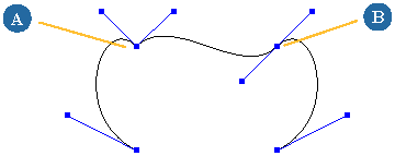
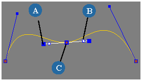
A pair of broken tangent handles (A) and a pair of aligned tangent handles (B).
You can break tangents manually using the Tweak Curve tool, or you can use the Make Bezier-Knot Corner command.
To break knots manually using the Tweak Curve tool
You can adjust Bézier tangent handles independently of each other with the middle mouse button while using the Tweak Curve tool. For more information about the Tweak Curve tool in general, see Using the Tweak Curve Tool.
After tangent handles have been broken, they can be realigned to make the curve smooth again at that point.
Choose one of the following commands from the Modify Curve menu on the Model toolbar:
Align Bezier Handles sets the slopes of both tangents to their average orientation.
Align Bezier Handles Back to Forward sets the slope of back tangent equal to the forward tangent.
Align Bezier Handles Forward to Back sets the slope of forward tangent equal to the back tangent.
"Back" and "forward" are considered in terms of the curve's parameterization from start to end point.
You can create straight segments on curves using the commands available on the Modify Curve menu of the Model toolbar, or on the context menu of the Tweak Curve tool. Softimage creates Bézier knots, if necessary,
and rotates the appropriate tangents to point at the adjacent knots. Once a straight segment has been created this way, the
Tweak Curve tool maintains the linearity when you move the adjacent knots. However, the segment will revert to a curve if
you adjust the tangent handles, or if you use a different tool to move control points.
To straighten segments adjacent to a knot
Right-click and choose one of the following commands from the context menu:
Make Adjacent Knot Segments Linear straightens both segments connected to the knot.
Make Fwd Knot Segment Linear straightens the forward segment.
"Back" and "forward" are considered in terms of the curve's parameterization from start to end point.


