


These are descriptions of the menu items in the UV Texture Editor.
Copies the selected UVs for a selected face to the clipboard so they can be copied (pasted) to another face. See Mesh > Clipboard Actions > Copy Attributes.
Pastes UVs that were previously copied to the selected face. See Mesh > Clipboard Actions > Paste Attributes.
Polygons > Create Empty UV Set
Creates a new, empty UV set on the current object. You can then create the UVs in the set using one of the mapping/projection methods. See Create UVs > Create Empty UV Set.
Use the items in this submenu to create a UV set based on an existing UV layout or transfer a UV layout from one set to another. See Create UVs > Copy UVs to UV Set.
Lets you select a specific UV set. See Create UVs > Set Current UV Set.
Polygons > Rename Current UV Set
Lets you rename the currently selected UV set. See Create UVs > Rename Current UV Set.
Polygons > Delete Current UV Set
Deletes the currently selected UV set. See Create UVs > Delete Current UV Set.
Scales the UVs of the selected faces to within the 0 to 1 texture space. See Edit UVs > Normalize.
Places the UVs of the selected faces on the boundary of the 0 to 1 texture space. See Edit UVs > Unitize.
Flips the positions of the selected UVs. See Edit UVs > Flip.
This item is also found on the UV Texture Editor toolbar for quick access. See UV Texture Editor toolbar.
Rotates the positions of the selected UVs by a specified number of degrees. See Edit UVs > Rotate.
This item is also found on the UV Texture Editor toolbar for quick access. See UV Texture Editor toolbar.
Rotates the U and V values of the selected polygon.
This item is also found on the UV Texture Editor toolbar for quick access. See UV Texture Editor toolbar.
Polygons > Best Plane Texturing Tool
Assigns UVs to the faces you select based on a plane computed from vertices you specify. See Create UVs > Best Plane Texturing Tool.
Moves every selected UV to its nearest grid intersection in texture space. See Edit UVs > Grid.
This item is also found on the UV Texture Editor toolbar for quick access. See UV Texture Editor toolbar.
Aligns the positions of the selected UVs. See Edit UVs > Align.
This item is also found on the UV Texture Editor toolbar for quick access. See UV Texture Editor toolbar.
Modifies a texture image by comparing two UV sets on a single polygonal mesh and produces a new bitmap image. See Edit UVs > Warp Image.
Moves UV borders to the edges of 0 to +1 texture space. See Edit UVs > Map UV Border.
Polygons > Straighten UV Border
Untangles the border of a UV texture shell, such as an edge that loops around itself. See Edit UVs > Straighten UV Border.
Spreads out all UVs to make them easier to work with. See Edit UVs > Relax.
This item is also found on the UV Texture Editor toolbar for quick access. See UV Texture Editor toolbar.
Lets you unwrap the UV mesh for a polygonal object while the feature attempts to ensure that the UVs do not overlap. See Edit UVs > Unfold.
Attempts to rearrange the UV shells into a cleaner layout, based on the settings in the Layout UVs option box. See Edit UVs > Layout.
This item is also found on the UV Texture Editor toolbar for quick access. See UV Texture Editor toolbar.
Separates UVs along the selected edges, creating borders. See Edit UVs > Cut UV Edges.
Separates UVs from each other along the edges connected to the selected UV points, creating borders. Shortcut for the texture editor’s Edit UVs > Split UVs.
This item is also found on the UV Texture Editor toolbar for quick access. See UV Texture Editor toolbar.
Attaches UVs along the selected borders, but does not move them together in the texture editor view. See Edit UVs > Sew UV Edges.
This item is also found on the UV Texture Editor toolbar for quick access. See UV Texture Editor toolbar.
Polygons > Move and Sew UV Edges
Attaches UVs along the selected borders, and moves them together in the texture editor view. See Edit UVs > Move and Sew UV Edges.
This item is also found on the UV Texture Editor toolbar for quick access. See UV Texture Editor toolbar.
Removes the selected UVs from the mesh. You will need to re-map or re-project the UVs in order to map textures onto the affected areas. See Edit UVs > Delete UVs.
Saves an image file of the current UV layout. You can then paint on this image in a painting program or use this image as a background reference layer for texture work in an image editor such as Adobe® Photoshop®. See Save an image of the UV layout. An option window appears with the following controls:
Normal (0 to 1) specifies the range between 0 and 1. When this option is set (default), only the UVs appearing in the 0 to 1 area are included in the 2D image that gets output.
Entire Range specifies that a 2D image will be output that covers all displayed UVs regardless of their position within UV space. That is, if the UVs lie outside the 0 to 1 range, they will still be included in the UV snapshot image.
User Specified allows you to customize the UV range that will be output by specifying minimum and maximum values for U and V. This is useful when you need to output an image of a specific UV shell or a specific region within the UV Texture Editor.
The items in this menu are used for editing UVs on subdivision surfaces.
Separates UVs along the selected edges, creating borders. See Edit UVs > Cut UV Edges.
Subdivs > Move and Sew UV Edges
Attaches UVs along the selected borders, and moves them together in the texture editor view. See Edit UVs > Move and Sew UV Edges.
Saves an image file of the current UV layout. For more information see Polygons > UV Snapshot.
A UV selection filter that displays only the UV faces associated with the currently selected UVs in the UV Texture Editor.
A UV selection filter that displays the UV faces associated with the currently selected UVs as well as the UV faces immediately connected to those UV faces.
View > View Faces of Selected Images
A UV selection filter that displays the UV faces associated with the currently selected texture image in the UV Texture Editor (Textures > filename).
Lets you show only a subset of all UVs, with the ability to add to and subtract from the isolated subset. See Display a subset of UVs
Shows or hides the texture coordinate grid. Choose View > Grid >  to set the grid options. See Use the UV Texture Editor grid
The items in this menu are also available on a marking menu when you are working in the UV Texture Editor. Press  +
+  to access them.
Select > Select Contained Faces
Selects the faces contained by the current selection of UVs, edges, or vertices.
Select > Select Connected Faces
Selects all faces that share the currently selected UVs, edges, or vertices.
Select > Select Shortest Edge Path Tool
Selects the shortest path of edges between two or more selection points (vertices or UVs). The Select Shortest Edge Path Tool determines the most direct path between any two selection points and selects the edges in between.
The Select Shortest Edge Path Tool is particularly well suited to selecting a long and possibly winding path of edges on a mesh when you need to subsequently perform a Cut UV Edges operation.
The items in this menu are also available from the toolbar.
Manipulates the layout of UVs as a group by letting you create a lattice around the UVs for deformation purposes.
Moves the position of selected UVs and their neighboring UVs to a diminishing extent that is user defined.
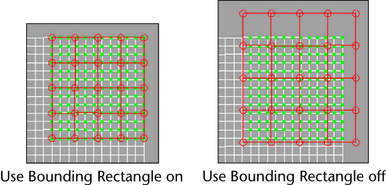
Lets you select and reposition a UV shell in the 2D view of the UV Texture Editor by selecting a single UV on the shell. You can automatically prevent the repositioned UV shell from overlapping other UV shells. See also UV Texture Editor toolbar.
The Prevent Overlap setting restricts a UV shell from being accidentally moved to a position where it would overlap existing UV shells in the UV Texture Editor view. It is on by default. For example, if you select and move a UV shell and reposition it to an area that is already occupied by an existing UV shell, the selected shell will do one of the following:
Specifies the number of times the tool checks between the start and end positions when translating one or more UV shells in order to optimally achieve the Shell Spacing distance without snapping back to the original location. A higher number produces the closest result possible, but takes longer to complete the move. The number of selected UV shells also affects the time to complete the move. The default setting is 16.
Let’s you interactively unfold or relax UVs. To use this tool, you must first select a set of UVs. Then, you can adjust the unfold or relax of the UVs by the respective control to the right. For more information, see Relax and untangle UVs or Unfold a UV mesh.
For more information on using the features in this menu see Display a texture behind the UVs.
Shows or hides the texture image. This item can also be found in the UV Texture Editor toolbar for quick access. See UV Texture Editor toolbar.
Reduces the brightness of the currently displayed background image. Dimming the background image lets you more easily view and select components in the UV Texture Editor’s view. Selecting the item toggles it on or off depending on its current state.
Turns off pixel blurring to show exact pixel boundaries. This item can also be found in the UV Texture Editor toolbar for quick access. See UV Texture Editor toolbar.
Shades active UV shells in a semitransparent way.
Image > Display RGB Channels, Display Alpha Channel
Switch between displaying the texture image and its alpha (transparency) channel. These items can also be found in the UV Texture Editor toolbar for quick access. See UV Texture Editor toolbar.
Determines whether or not to automatically snap UVs to pixels. Snapping is to pixel corners or centers. This item can also be found in the UV Texture Editor toolbar for quick access. See UV Texture Editor toolbar.
Switches between showing square texture space and texture space with the same ratio of width to height as the image. This item can also be found in the UV Texture Editor toolbar for quick access. See UV Texture Editor toolbar.
Image > UV Texture Editor Baking
Bakes the texture and stores it in memory. See also UV Texture Editor toolbar.
Creates an Adobe® Photoshop® texture you can use as a texture map. When this feature is used, a PSD layer of the UVs can be explicitly created to aid painting of the texture. For more information, see Use PSD Networks as textures in Maya and Create a PSD file with layer sets from within Maya in the Shading guide.
When you modify a PSD file in Adobe® Photoshop® that is connected to a Maya PSD node, you can update (refresh) the image in Maya to show the modifications immediately. All PSD networks in the scene are updated. See Update PSD Networks in the Shading guide.
Select which image texture to show in the UV Texture Editor. Select an image from the drop-down list that appears. If no texture images are assigned the list appears empty.
Select the UV set you want to edit in the UV Texture Editor by selecting the name of the UV set from the drop-down list that appears. See UV sets.
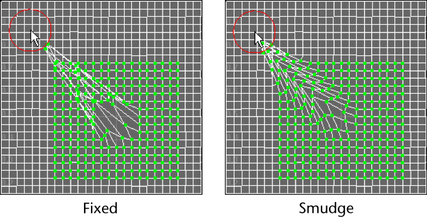
 -drag to smudge the layout of your UVs. When off, drag to smudge the layout of your UVs.