In this section, you will create grooves to represent styled air intakes.
Opening the tutorial file (optional)
If you successfully completed Part 4, you can proceed directly to the next step, Creating the groove surfaces.
If you were not successful in part 4, open the file called vacuum_part5.wire, located in the wire directory of the CourseWare project. This file contains the completed model from Part 4.

Watch Part 5 of the tutorial.
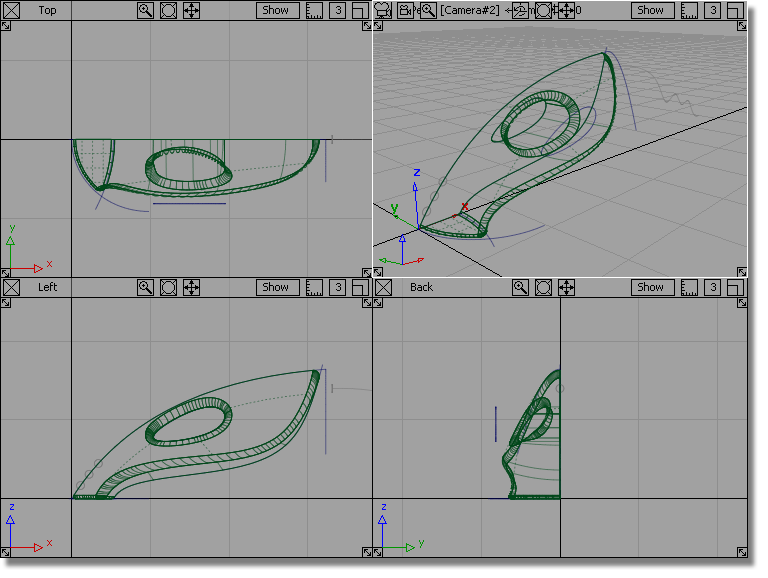
The groove surfaces will be created from three extruded tube shapes. The profile of the tubes will be circular, and the path will follow the general shape of the main body. To create an interesting intersection line, the path curve will pull away from the body shape so the grooves fade out at the outer edge.
To match the character of the main body shape, you will use the original nozzle curve as a path to extrude the three groove surfaces.
 and select the front nozzle
curve.
and select the front nozzle
curve.

 followed by Edit > Paste
  to create a copy of the
curve.
to create a copy of the
curve.

 to deselect the curve.
This scaled curve will be used as a path curve for the extruded surfaces.
The three gray circles at the front of the vacuum cleaner have been templated. You will now untemplate these so you can use them as the generation curves for the extrude surfaces.
 and drag a pick box around
the three circles.
and drag a pick box around
the three circles.
 to return the curves to
pickable geometry.
to return the curves to
pickable geometry.
You will now extrude the circles along the path curve.
 . You are prompted to select
curve(s) to extrude.
. You are prompted to select
curve(s) to extrude.
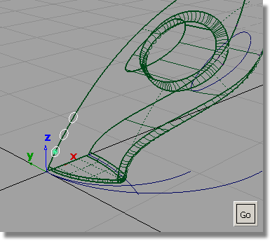
Click Go to select the circles for extrusion.

Three surfaces are created, following the shape of the upper surface.

Intersecting and Trimming the air vents
You will now intersect and trim the three extruded surfaces with the upper surface of the vacuum body.
 .
.
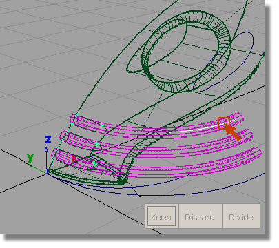
The three extruded surfaces are highlighted in pink, indicating they are selected for intersecting.
Pick the upper surface of the vacuum.

The surfaces are intersected and the curves-on-surface created.
Now, you will trim the excess from the surfaces, starting with the extruded surfaces. In this trimming operation, it is easier to select the part of the surfaces you want to discard, so you will use the Discard option in the trim tool, instead of the Keep option.
and drag a pick box to select
the three extruded surfaces.
 .
.
The surfaces are highlighted in pink, and you are prompted to select the regions to trim.
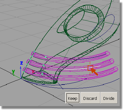

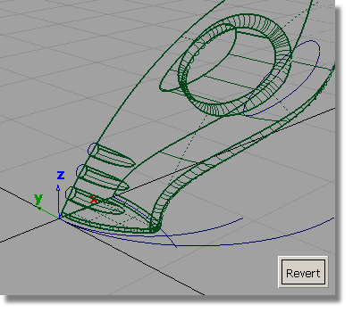
The excess surfaces are discarded.
Next, you will trim the upper surface.
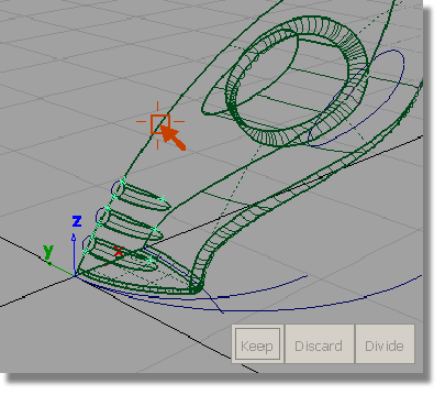

An indicator is placed where you clicked and three buttons appear in the bottom right corner of the view.

The upper surface is trimmed.
to complete the trimming
operation.
Now that you have created all the main surfaces, you will make the curves layer invisible, so the surfaces can be viewed more clearly.
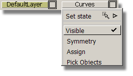
In the Layer Bar, the curves layer is displayed with a dotted outline to indicate it is turned off.

The curves are no longer displayed on the screen.

 to save the current scene.


