The Terrain compound object creates planet surfaces from contour-line data.
To produce a terrain, you select editable splines representing elevation contours and then click Terrain, whereupon 3ds Max generates a mesh surface over the contours. You can also create a "terraced" representation of the terrain object so that each level of contour data is a step, resembling traditional study models of land forms.
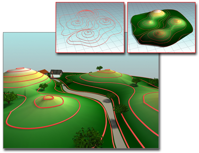
Using contours to build a terrain
Inset left: The contours
Inset right: The terrain object
Main: Terrain object used as the basis of a landscape
You can import an AutoCAD drawing file to use as contour data. When you do so, 3ds Max names each object based on the AutoCAD object's layer, color, or object type, appending a number to each name. For example, an AutoCAD object on the layer BASE becomes an object named BASE.01. See Importing DWG Files for more information.
After you import or create the contour data, select the objects, and click the Terrain button, 3ds Max creates a new triangulated mesh object based on the contour data. The name of the first selected spline becomes the name of the terrain object. Other splines in the selection are treated according to the previously set Reference, Move, Copy, or Instance selection in the Pick Operand rollout, described below.
Keep in mind that the Terrain object can use any spline objects as operands, whether they are horizontal splines or not. Though the most common scenario is when sets of elevational contours are used to create terrain forms, it is possible to append or refine Terrain objects by using non-horizontal splines.
 Geometry Options group Cap Closed Entities.
Following are examples of uses of the Terrain feature:
 Select the contour data, then click the Terrain button.
3ds Max displays the zones in the list under the Create Defaults button.
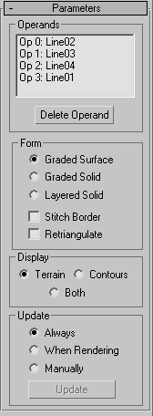
Displays the name of the terrain object. 3ds Max uses the name of one of the selected objects to name the terrain object.
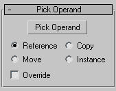
Adds splines to the terrain object. You might do this if you didn't select all the objects before generating the terrain object, or if some objects in the imported data weren't included in the terrain object. You can also use this option to add existing splines in the current scene to the terrain object.
When you click Pick Operand, the copy method you designate determines how the operands are used. When Move is the method, the original contour data is moved from the scene and into the operands of the new terrain object. Copy, Reference, and Instance retain the original contour data in the scene and create copies, references or instances of the contour data as operands in the terrain object. This is similar to the copy method for Boolean.
Allows you to select closed curves that override any other operand data within their interior. Within the area an Override operand encloses (as seen in plan), other curves and points of the mesh are disregarded and the elevation of the Override operand supersedes them. An Override operand is indicated in the operands list by a # after its name. Override is only effective on closed curves. If multiple override operands overlap, later overrides (higher operand numbers) take preference.
Displays the current operands. Each operand is listed as "Op" followed by a number and the name of the object that is being used as the operand. The operand name comprises layer, color, or object type name plus a numeric suffix.
Use standard mouse-based methods to highlight list members: Click to highlight a single entry; drag or Shift+click to highlight a range; Ctrl+click to toggle highlighting of a single entry without changing other entries’ status.
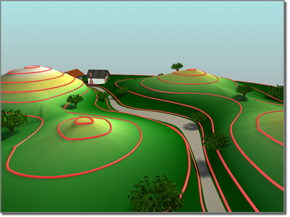
Terrain created as a graded surface
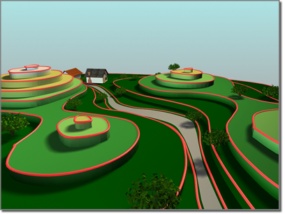
Terrain created as a "layered solid" surface, with levels
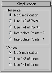
The basic Terrain algorithm tends to flatten or notch contours when they turn sharply upon themselves. A typical situation in which this may happen is when a narrow creek bed is described with contours; the resulting form may look more like a series of cascades at each elevational contour, rather than a smoothly descending ravine. When Retriangulate is checked, a somewhat slower algorithm is used that follows contour lines more closely. This may be particularly evident in the Layered Solid display mode. For additional precision, try using Retriangulate in conjunction with horizontal interpolation.
The items in this group box determine when 3ds Max recalculates the projection for the terrain object. Because complex terrain objects can slow performance, you can use these options to avoid constant calculation.
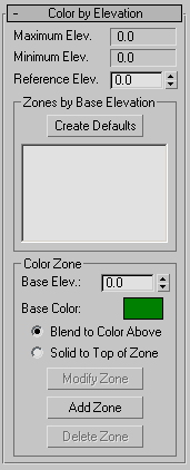
This is the reference elevation, or datum, that 3ds Max uses as a guide for assigning colors to zones of elevation. After entering a reference elevation, click the Create Defaults button. 3ds Max treats elevations above the reference elevation as solid land and those below the reference elevation as water.
If you enter a value no greater than the minimum elevation in the object, 3ds Max divides the range between the reference and minimum elevations into five color zones: dark green, light green, yellow, purple, and light gray.
If you enter a value between the minimum and maximum elevations, 3ds Max creates six color zones. Two zones (dark blue and light blue) are used for elevations below the reference elevation. These are considered to be under water. One zone (dark yellow) is used for a narrow range around the reference elevation. Three zones (dark green, light green, light yellow) are used for elevations above the reference elevation.
If you enter a value at or above the maximum elevation, 3ds Max divides the range between the minimum and reference elevations into three zones (dark blue, medium blue, light blue).
Creates elevation zones. 3ds Max lists the elevation at the bottom of each zone, referenced to the datum (the reference elevation). 3ds Max applies the color of the zone at the base elevation. Whether the colors blend between zones depends on your choice of the Blend to Color Above or Solid to Top of Zone option.


 Create panel
  (Geometry)