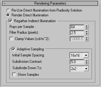
Provides parameters for controlling how to render the radiosity-processed scene.
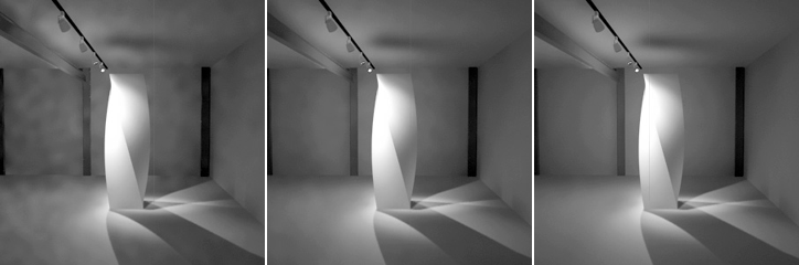
By default, when you render, 3ds Max first recalculates the shadows from light objects, and then adds the result of the radiosity mesh as ambient light.
The first two options on the rollout control how the renderer treats direct illumination. Re-Use Direct Illumination From Radiosity Solution provides a quick render that displays colors from the radiosity mesh. Render Direct Illumination uses the scanline renderer to provide direct illumination and shadows. This second option is usually slower but more accurate. With Render Direct Illumination, the radiosity solution provides only the indirect lighting.
When you choose the Render Direct Illumination method, you can turn on regathering to correct artifacts and shadow leaks. Regathering provides the slowest but the best-quality rendering.
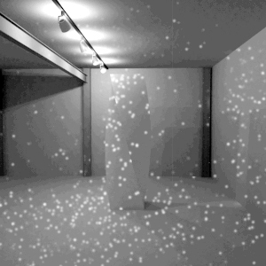
3ds Max doesn’t render direct lights, but uses the direct lighting stored in the radiosity solution. If you turn on this option, the Regather Indirect Illumination option is disabled. The quality of shadows in the scene depends on the mesh resolution. Capturing fine shadow details might require a fine mesh, but in some situations this option can speed up overall rendering time, especially for animations, because the lights don’t have to be recalculated by the scanline renderer.
If you are using the Assign Vertex Colors utility, turn this option on.
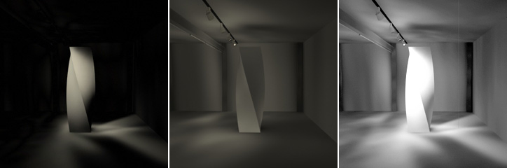
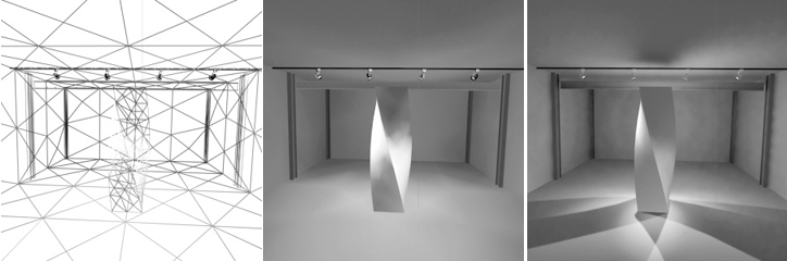
Left: Direct light only is stored in the radiosity mesh.
Middle: Indirect light only is stored in the radiosity mesh.
Right: Direct and indirect light both stored in the radiosity mesh (the shadows are usually very coarse).
3ds Max renders shadows from the lights at each rendering frame, and then adds indirect light from the radiosity solution. This is the default rendering mode.
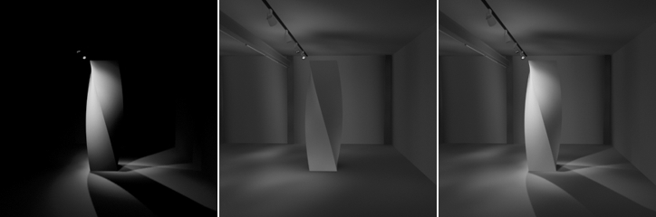
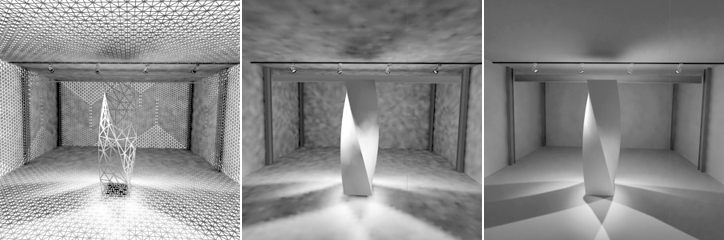
Left: Direct light calculated only by the scanline renderer.
Middle: Indirect light calculated only by the radiosity mesh.
Right: Direct and indirect light combined.
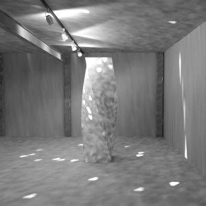
In addition to recalculating all the direct lighting, 3ds Max recalculates the indirect lighting at each pixel by regathering illumination data from the existing radiosity solution. Using this option can produce the most accurate, artifact-free images, but it can add a considerable amount of rendering time.
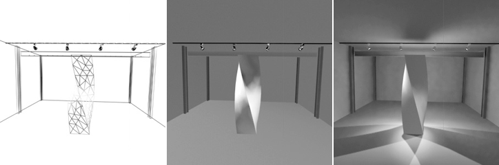
In the following illustrations, solutions were processed with an Initial Quality of 0%. There is a high variance between small surfaces when a dense mesh is used. Regathering gives acceptable results regardless of mesh density. But more subtle details appear with a denser mesh; for example, at the base of the sculpture.
No mesh
Left: Model subdivision
Middle: Viewport result
Right: Result of regathering
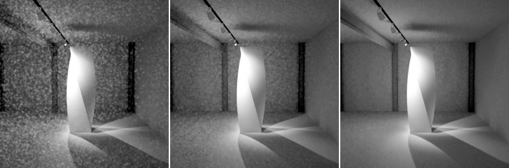
Coarse mesh
Left: Model subdivision
Middle: Viewport result
Right: Result of regathering
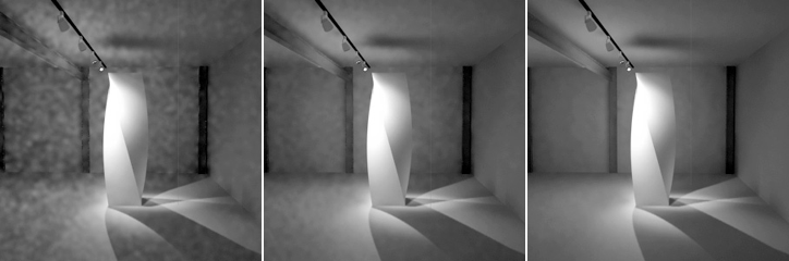
Fine mesh
Left: Model subdivision
Middle: Viewport result
Right: Result of regathering
The number of rays 3ds Max casts for each sample. 3ds Max casts these rays randomly in all directions to calculate (“regather”) the indirect illumination from the scene. The more rays per sample, the more precise the sample will be. Fewer rays per sample produce more variance, creating a more grainy effect. Processing speed and precision are affected by this value. Default=64.
Averages each sample with its neighbors in order to reduce the noisy effect. Default=2.5 pixels.
Pixel radius of 2
Left: 10 rays per sample
Middle: 50 rays per sample
Right: 150 rays per sample
Pixel radius of 5
Left: 10 rays per sample
Middle: 50 rays per sample
Right: 150 rays per sample
Pixel radius of 10
Left: 10 rays per sample
Middle: 50 rays per sample
Right: 150 rays per sample
Increasing the number of rays per sample can greatly increase rendering time. The images on the right can take nearly six times as long to render as the images on the left. Increasing the filter radius also increases render time, but not as dramatically.
This control is expressed as a luminance value. Luminance (candelas per meter squared) represents how brightly you perceive a material. Clamp Value sets an upper limit on the luminance that will be considered in the Regathering stage. Use it to avoid the appearance of bright spots.
Bright polygons in the scene can create a “sparkle” effect of bright spots.
These bright spots are artifacts not of the number of samples cast, but rather of the presence of bright polygons in your scene. During the Initial Quality stage, this bright energy gets bounced in random directions, leading to a “sparkle” effect. Typically you can detect these polygons before regathering.
During the final Regathering stage, bright spots can be avoided by setting Clamp Values somewhat below the luminance of these bright surfaces and spots.
Bright spots have been reduced by clamping.
Be careful with this control: Clamp Values let you clamp any intensity, and the rendering might become darker than it should be because you have clamped indirect illumination that is to be expected, thus dimming the effect of the radiosity solution.
These controls can help you shorten rendering times. They reduce the number of light samples taken. The ideal settings for adaptive sampling vary greatly from scene to scene.
Adaptive sampling initially takes samples from a grid superimposed on the pixels of the scene. Where there is enough contrast between samples, it subdivides that region and takes further samples, down to the minimum area specified by Subdivide Down To. Lighting for areas not directly sampled is interpolated.


 (Render Setup)