


Radiosity is rendering technology that realistically simulates the way in which light interacts in an environment.
This topic provides you with a conceptual overview of what radiosity is and how this global illumination technique relates to other rendering techniques available in 3ds Max. This information will help you decide which technique is most suitable for the visualization task you want to perform. By more accurately simulating the lighting in your scene, radiosity offers you significant benefits over standard lights:
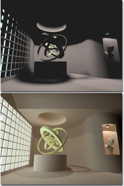
Top: A scene rendered without radiosity.
Bottom: The same scene rendered with radiosity.
The 3D models created in 3ds Max contain geometric data defined in relationship to a 3D Cartesian coordinate system, referred to as world space. The model also contains other information about the material of each of the objects and the lighting in the scene. The image on a computer monitor is made up of many illuminated dots, called pixels. The task in creating a computer graphics image of a geometric model is to determine the color for each pixel based on the model information and a specific viewpoint (camera).
The color of any specific point on a surface in a model is a function of the physical material properties of that surface and the light that illuminates it. Two general shading algorithms: local illumination and global illumination are used to describe how surfaces reflect and transmit light.
Local illumination algorithms describe only how individual surfaces reflect or transmit light. Given a description of light arriving at a surface, these mathematical algorithms, called shaders in 3ds Max, predict the intensity, color, and distribution of the light leaving that surface. In conjunction with a material description, different shaders will determine, for example, if a surface will appear like plastic or metal or if it will appear smooth or rough. 3ds Max provides a robust interface for defining a wide array of different surface materials.
After defining how an individual surface interacts with light at the local level, the next task is to determine where the light arriving at the surface originates. With the standard scanline rendering system of 3ds Max, only the light coming directly from the light sources themselves is considered in the shading.
For more accurate images, however, it is important to take into account not only the light sources, but also how all the surfaces and objects in the environment interact with the light. For example, some surfaces block light, casting shadows on other surfaces; some surfaces are shiny, in which case we see in them the reflections of other surfaces; some surfaces are transparent, in which case we see other surfaces through them; and some surfaces reflect light onto other surfaces.
Rendering algorithms that take into account the ways in which light is transferred between surfaces in the model are called global illumination algorithms. 3ds Max offers two global illumination algorithms as an integral part of its production rendering system: ray-tracing and radiosity.
Before an explanation of how ray-tracing and radiosity work, it’s useful to understand how light is distributed in the physical world. Consider, for example, the room shown in the illustration below.
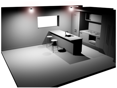
Kitchen lit by two lights
This kitchen above has two light sources. One theory of light considers the light in terms of discrete particles called photons, that travel from the light source until they encounter some surface in the kitchen. Depending on the surface material, some of these photons are absorbed and others are scattered back out into the environment. The fact that photons traveling at a particular wavelength are absorbed while others are not is what determines the color of the surface.
Surfaces that are very smooth reflect the photons in one direction, at an angle equal to the angle at which they arrive at the surface, the angle of incidence. These surfaces are known as specular surfaces, and this type of reflection is known as specular reflection. A mirror is an example of a perfectly specular surface. Of course, many materials display some degree of both specular and diffuse reflection.
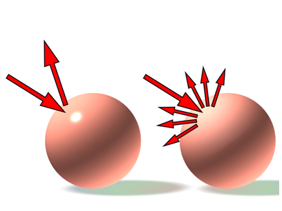
Left: Specular reflection
Right: Diffuse reflection
The way in which the photons are reflected from a surface depends primarily on the smoothness of the surface. Rough surfaces tend to reflect photons in all directions. These are known as diffuse surfaces, and this type of reflection is known as diffuse reflection (shown above). A wall painted with flat paint is a good example of a diffuse surface.
The final illumination of the kitchen is determined by the interaction between the surfaces and the billions of photons emitted from the light source. At any given point on a surface, it is possible that photons have arrived directly from the light source (direct illumination) or else indirectly through one or more bounces off other surfaces (indirect illumination). If you were standing in the kitchen, a very small number of the photons in the room would enter your eye and stimulate the rods and cones of your retina. This stimulation would, in effect, form an image that is perceived by your brain.
In computer graphics we replace the rods and cones of a retina with the pixels of the computer screen. One goal of a global illumination algorithm is to re-create, as accurately as possible, what you would see if you were standing in a real environment. A second goal is to accomplish this task as quickly as possible, ideally in real time (30 images per second). Currently, no single global illumination algorithm can accomplish both goals.
One of the first global illumination algorithms developed is known as ray-tracing. The ray-tracing algorithm recognizes that although billions of photons may be traveling about the room, the photons we primarily care about are the ones that enter the eye. The algorithm works by tracing rays backward, from each pixel on the screen into the 3D model. In this way, we compute only the information needed to construct the image. To create an image using ray-tracing, the following procedure is performed for each pixel on the computer screen.
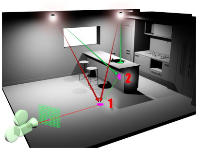
Ray-tracing: Rays are traced from the camera through a pixel, to the geometry, then back to their light sources.
The ray-tracing algorithm is very versatile because of the large range of lighting effects it can model. It can accurately account for the global illumination characteristics of direct illumination, shadows, specular reflections (for example, mirrors), and refraction through transparent materials. The main disadvantage of ray-tracing is that it can be very slow for environments of even moderate complexity. In 3ds Max, ray-tracing is used selectively on objects with ray-trace materials that specify ray-tracing as their shading option. Ray-tracing can also be specified for light sources as the method for rendering the shadows they cast.
A significant disadvantage of both ray-tracing and scanline rendering is that these techniques do not account for one very important characteristic of global illumination, diffuse inter-reflections. With traditional ray-tracing and scanline rendering, only the light arriving directly from the light sources themselves is accurately accounted for. But, as shown in the room example, not only does light arrive at a surface from the light sources (direct lighting), it also arrives from other surfaces (indirect lighting). If we were to ray-trace an image of the kitchen, for example, the areas in shadow would appear black because they receive no direct light from the light sources. We know from experience, however, that these areas would not be completely dark because of the light they would receive from the surrounding walls and floor.
In scanline rendering and traditional ray-tracing (versions of 3ds Max prior to v5), this indirect illumination is usually accounted for simply by adding an arbitrary ambient light value that has no correlation to the physical phenomena of indirect illumination and is constant throughout space. For this reason, scanline and ray-traced images can often appear very flat, particularly renderings of architectural environments, which typically contain mostly diffuse surfaces.
To address this issue, researchers began investigating alternative techniques for calculating global illumination, drawing on thermal engineering research. In the early 1960s, engineers developed methods for simulating the radiative heat transfer between surfaces to determine how their designs would perform in applications such as furnaces and engines. In the mid-1980s, computer graphics researchers began investigating the application of these techniques for simulating light propagation.
Radiosity, as this technique is called in the computer graphics world, differs fundamentally from ray-tracing. Rather than determining the color for each pixel on a screen, radiosity calculates the intensity for all surfaces in the environment. This is accomplished by first dividing the original surfaces into a mesh of smaller surfaces known as elements. The radiosity algorithm calculates the amount of light distributed from each mesh element to every other mesh element. The final radiosity values are stored for each element of the mesh.
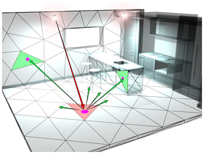
Radiosity: A ray of light that hits a surface is reflected by multiple diffuse rays, which can themselves illuminate other surfaces. Surfaces are subdivided to increase accuracy of the solution.
In early versions of the radiosity algorithm, the distribution of light among mesh elements had to be completely calculated before any useful results could be displayed on the screen. Even though the result was view-independent, the preprocessing took a considerable amount of time. In 1988, progressive refinement was invented. This technique displays immediate visual results that can progressively improve in accuracy and visual quality. In 1999, the technique called stochastic relaxation radiosity (SRR) was invented. The SRR algorithm forms the basis of the commercial radiosity systems provided by Autodesk.
Although the ray-tracing and radiosity algorithms are very different, they are in many ways complementary. Each technique has advantages and disadvantages.
Neither radiosity nor ray-tracing offers a complete solution for simulating all global illumination effects. Radiosity excels at rendering diffuse-to-diffuse inter-reflections, and ray-tracing excels at rendering specular reflections. By integrating both techniques with a production quality scanline rendering system, 3ds Max offers the best of both worlds. After you create a radiosity solution, you can render a two-dimensional view of it. In your 3ds Max scene, ray-tracing adds effects in addition to those that radiosity provides: lights can provide ray-traced shadows, and materials can provide ray-traced reflections and refractions. The rendered scene combines both techniques, and appears more realistic than either technique alone could provide.
By integrating ray-tracing and radiosity, 3ds Max offers a full range of visualization possibilities, from fast, interactive lighting studies to images of exceptional quality and realism.
This topic provides an overview of how radiosity works in 3ds Max.
This topic describes how to set up a scene for use with radiosity. Considerations include the size of the scene and the measuring system, the lighting, and the materials used in the scene.
By default, a radiosity solution is calculated at the current frame. If you are animating objects and you want to perform a radiosity solution at every frame, turn on Compute Advanced Lighting When Required in the Render Setup dialog Common panel Common Parameters rollout Advanced Lighting group.
Radiosity is a technique to calculate indirect light. Specifically, radiosity calculates the interreflections of diffuse light among all the surfaces in a scene. To make this calculation, radiosity takes into account the lighting, materials, and environment settings in the scene.
To query light levels, analyze the data, and produce reports, use the Lighting Analysis dialog. This dialog provides rendering data on material reflectance, transmittance, and luminance.