Command entry:
Select a Loft object.


Modify panel
Deformations rollout
Scale, Twist, Teeter, Bevel, or Fit
The Deformation dialogs for Scale, Twist, Teeter, Bevel, and Fit use the same basic layout.
The buttons in the window's toolbar and prompt area perform the following functions:
- Change deformation curve display.
- Edit control points (these can be animated).
- Navigate the Deformation dialog.
Editing Deformation Curves
A deformation curve starts as a straight line using a constant value. To produce more elaborate curves, you insert control
points and change their properties.
Use the buttons in the center of the Deformation dialog toolbar to insert and change deformation curve control points (see
Interface, later in this topic).
Control Point Types
Control points on a deformation curve can produce curves or sharp corners, depending on the control point type. To change
a control point type, right-click the control point and choose one of these from the shortcut menu:
- Non-adjustable linear control point producing a sharp corner.
- Adjustable Bezier control point with discontinuous tangent handles set to produce a sharp corner. This type produces a curve
that looks like the corner type but has control handles like the Bezier Smooth type.
- Adjustable Bezier control point with locked continuous tangent handles set to produce a smooth curve.
Selecting Control Points
Use the Move Control Point and Scale Control Point buttons with standard selection techniques to select control points.
Procedures
To drag Bezier tangent handles:
-
 Select one or more Bezier Smooth or Bezier Corner control points to display their tangent handles.
- Click one of the Move Control Point buttons.
- Drag any tangent handle.
- Only the tangent handle you drag is affected. Tangent handles on other selected control points do not change.
- If the tangent handle you drag is part of a Bezier Smooth control point, both handles move to maintain the Bezier Smooth type.
- If the tangent handle you drag is part of a Bezier Corner control point, only that handle moves.
To move a control point using the Position and Amount fields:
- Select a single control point.
- Do one of the following:
- Move the control point horizontally by entering a value in the Position field.
- Move the control point vertically by entering a value in the Amount field.
To change the control point type:
You can change control point types at any time by right-clicking a selection of one or more control points.
- Select one or more control points.
- Right-click any selected control point.
- Choose a control point type from the shortcut menu.
The following conditions apply to changing control point types:
- The first and last control points must use the Corner or Bezier Corner type.
- Converting a Bezier Smooth point to a Bezier Corner point unlocks the tangent handles but does not change their position.
The curve appears smooth until you drag one of the tangent handles.
- Converting a Bezier Corner point or inserted Bezier point to Bezier Smooth locks the tangent handles and changes their position
and magnitude. The handles are rotated to the average between their two angles. The handle magnitudes are averaged and set
equal.
Interface
Toolbar
Buttons for working with a second curve are disabled for the Twist and Bevel deformations, which use only one curve. The disabled
buttons are Make Symmetrical, Display X Axis, Display Y Axis, Display XY Axes, and Swap Deform Curves.
-
 Make Symmetrical
-
You can apply the same deformation to both axes of a shape using Make Symmetrical, which is both an action button and a curve
editing mode. Turning on Make Symmetrical has the following effect:
- When a single curve is displayed, it copies the displayed deformation curve to the curve for the hidden axis.
- When both axes are displayed, the Apply Symmetry dialog is also displayed. Click the button for the curve you want to apply
to both axes.
- Changes you make to the selected curve are duplicated on the other curve.
When Make Symmetrical is not active, curve editing is applied only to the selected curve.
- Display X Axis / Y Axis / XY Axes
-
You can display one or both deformation curves using the curve display buttons near the upper-left corner of the Deformation
dialog.
Turn on the following buttons to display deformation curves:
-
 Displays only the X axis deformation curve in red.
-
 Displays only the Y axis deformation curve in green.
-
 Displays X axis and Y axis deformation curves together, each using its own color.
-
 Swap Deform Curves
-
Copies curves between the X axis and Y axis. This button is disabled when Make Symmetrical is on.
Click Swap Deform Curves to copy the X axis curve to the Y axis, and the Y axis curve to the X axis. It doesn't matter which
curve is currently displayed or selected.
- Move Control Points
-
This flyout contains three buttons for moving control points and Bezier handles:
-
 Changes the amount of deformation (vertical movement) and the location of the deformation (horizontal movement).
-
 Changes the amount of deformation without changing the location.
-
 Changes the location of the deformation without changing the amount.
If one control point is selected, you can move it by entering values in the control point Position and Amount fields at the
bottom of the Deformation dialog.
You cannot move end points horizontally. Intermediate control points are constrained horizontally to stay between the points
on either side. The amount of horizontal constraint is determined by the control point type.
- You can move corner control points very close together, until one is directly above the other.
- You can move Bezier control points no closer than the length of their tangent handles.
- Moving Bezier Tangent Handles
-
You can use the Move Control Point buttons to drag a tangent handle's angle and magnitude on Bezier Smooth and Bezier Corner
vertices.
Dragging a tangent handle has the following constraints:
- You cannot move tangent angles beyond vertical. This prevents deformation curves from doubling back on themselves.
- You cannot move tangent magnitudes beyond the preceding or next control point on the path.
Pressing Shift while moving a Bezier Smooth tangent handle converts the control point to a Bezier Corner type.
-
 Scale Control Point
-
Scales the value of one or more selected control points with respect to 0. Use this function when you want to change only
the deformation amounts of selected control points while maintaining their relative ratio of values.
- Drag downward to reduce values.
- Drag upward to increase values.
- Insert Control Point
-
This flyout contains buttons for inserting two control point types.
-
 Insert Corner Point
-
Click anywhere on a deformation curve to insert a corner control point at that location.
-
 Insert Bezier Point
-
Click anywhere on a deformation curve to insert a modified Bezier control point at that location. The tangent handles of the
Bezier control point are set to maintain the shape of the curve before the point was inserted.
If you are not sure which type of control point you need, or if you change your mind, you can convert the point to another
type by right-clicking the point and selecting the type from the shortcut menu.
Both Insert Control Point buttons put you in insertion mode. Right-click or choose another button to exit the mode.
-
 Delete Control Point
-
Deletes selected control points. You can also delete selected points by pressing the Delete key.
-
 Reset Curve
-
Deletes all but the end control points and sets the curves back to their default values.
- Bevel Type
-
This flyout, available only in the Bevel Deformation dialog, lets you choose Normal, Adaptive Linear or Adaptive Cubic as
the bevel type. For more information, see Deform Bevel.
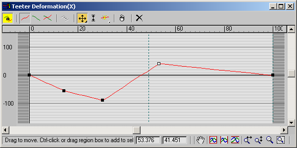
Deformation grid
The area in the Deformation dialog that displays the deformation curves is called the deformation grid. This grid charts the
value of the deformation along the length of the path.
These are the main grid components:
- Active area
-
The light-colored area of the grid defines the first and last vertex boundaries of the path. The ends of the deformation curve
lie on each boundary and cannot be moved off the boundary.
- Horizontal lines
-
Mark deformation values on the vertical scale. The following table lists each deformation curve type and the meaning of the
deformation values.
| Deformation Type |
Deformation Value |
| Scale |
Percentage |
| Twist |
Rotation Angle |
| Teeter |
Rotation Angle |
| Bevel |
Current Units |
The thick horizontal line at 0 represents the deformation value at the loft path.
- Vertical lines
-
Mark levels of the path. The levels displayed vary with the Adaptive Path Steps setting on the Skin Parameters rollout.
If Adaptive Path Steps is on, levels are displayed at all path vertices and shape locations.
If Adaptive Path Steps is off, levels are displayed only at path vertices.
- Path ruler
-
Measures the length of the path. The values on the ruler measure percentage along the path. You can drag the path ruler vertically
in the Deformation dialog.
- Deformation curves
-
You can see one or two curves in the Deformation dialog, based on the deformation type and the curve display setting. The
curves are color-coded by axis.
A red curve displays deformation along the shape's local X axis. A green curve displays deformation along the shape's local
Y axis.
- Control Point fields
-
At the bottom of the Deformation dialog are two edit fields. When a single control point is selected these fields display
the path location and deformation amount of the control point.
- Control Point Position
-
The left field displays the location of the control point on the loft path as a percentage of the total path length.
- Control Point Amount
-
The right field displays the deformation value of the control point.
Deformation Dialog status bar
The Deformation dialogs have their own view navigation buttons in the lower-right corner. These give you controls for zooming
and panning the view of the deformation grid as you edit the curve values. The status bar also displays information about
the current tool and the selected control point.
- Numeric fields
-
These two fields are accessible only if a single control point is selected. The first gives the point's horizontal position,
and the second gives its vertical position, or value. You can edit these fields with the keyboard.
-
 Lock Aspect
-
This button is present only in the Fit Deformation dialog. When active, it restricts zooming to vertical and horizontal at
the same time.
-
 Zoom Extents
-
Changes the view magnification so the entire deformation curve is visible.
-
 Zoom Horizontal Extents
-
Changes the view magnification along the path length so the entire path area is visible in the dialog.
-
 Zoom Vertical Extents
-
Changes the view magnification along the deformation values so the entire deformation curve is displayed in the dialog.
-
 Zoom Horizontally
-
Changes magnification along the path length.
- Drag to the right to increase magnification.
- Drag to the left to decrease magnification.
- Zoom Vertically
-
Changes magnification along the deformation value.
- Drag upward to increase magnification.
- Drag downward to decrease magnification.
-
 Zoom
Zoom
-
Changes magnification along both the path length and the deformation value, preserving the curve aspect ratio.
- Drag upward to increase magnification.
- Drag downward to decrease magnification.
-
 Zoom Region
-
Drag a region on the deformation grid. The region is then magnified to fill the deformation dialog.
-
 Pan
Pan
-
Drag in the view to move in any direction.
- Scroll bars
-
Drag the horizontal and vertical scroll bars to pan the view in a single direction.