Command entry:
Select a path or shape.


Create panel

(Geometry)
Compound Objects
Object Type rollout
Loft
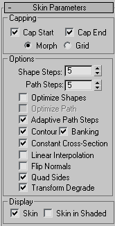
Skin Parameters rollout
Command entry:Select a path or shape.
Create menu
Compounds
Loft
Skin Parameters rollout
On the Skin Parameters rollout, you adjust the complexity of the mesh of the loft object. You can also optimize the mesh by
controlling the face count.
Procedures
Example: To use a constant cross-section:
-
 Maximize the Front viewport, and then draw a Rectangle object with Ctrl held down, to create a square about 20 x 20 units.
- Create another rectangle beside it about 200 x 100 units.
- Apply a Skew modifier to the large rectangle, but don't alter the Skew parameters.
- Create a loft object in which the larger rectangle is the path and the square is the shape.
- On the
 Modify panel, open the Skin Parameters rollout, and make sure Skin is on in the Display group.
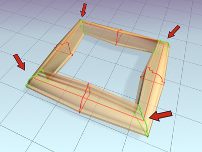
You can now see the wireframe structure of the lofted rectangle, with cross-sectional sides parallel to its corners.
Make sure the color assigned the loft object is easily visible. Change it if necessary.
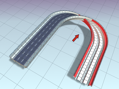
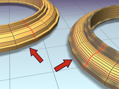
- Turn off Constant Cross-Section, and observe the corners.
When Constant Cross-Section is off, the corners become pinched.
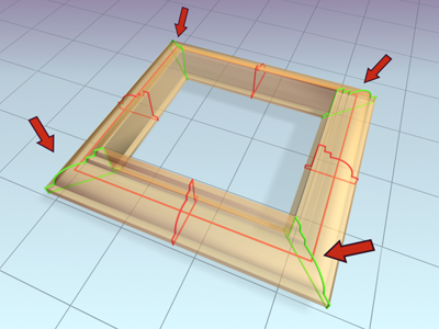
- Turn on Constant Cross-Section to restore the corners.
Acute angles can cause problems when the cross sections formed by the path steps intersect at the corners. You can mitigate
this by avoiding acute angles or by reducing the path steps.
- Press H on the keyboard to open the Select From Scene dialog, and select Rectangle02 (the second larger rectangle).
- On the Modify panel, change the Skew Axis to Y, and then set the Amount spinner to 95.
- Use
 (Zoom Region) to zoom in on the upper-right corner of the rectangle so you can see the mesh in detail.
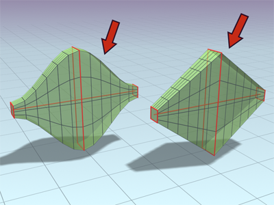
At a skew of less than 100, the acute angle still works because the path cross-sections haven't intersected.
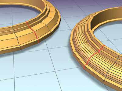
- Set the Skew Amount to 300, and examine the same corner.
At this angle, the path cross sections intersect, causing problems in the mesh.
-
 Select the loft object, and set Path Steps to 1.
The cross sections no longer intersect, and the corner is clean.
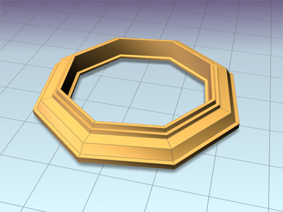
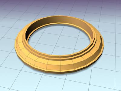
When creating straight-edge molding for architectural modeling, you can avoid mangled corners simply by reducing the path
steps to 0.
Interface
Capping group
- Cap Start
-
Whenon, the end of a loft at the first vertex of the path is covered, or capped. When off, the end is open, or uncapped. Default=on.
- Cap End
-
When on, the end of a loft at the last vertex of the path is covered, or capped. When off, the end is open, or uncapped. Default=on.
- Morph
-
Arranges cap faces in a predictable, repeatable pattern necessary for creating morph targets. Morph capping can generate long,
thin faces that do not render or deform as well as those created with grid capping.
- Grid
-
Arranges cap faces in a rectangular grid trimmed at the shape boundaries. This method produces a surface of evenly sized faces
that can be deformed easily by other modifiers.
Options group
- Shape Steps
-
Sets the number of steps between each vertex of the cross-section shapes. This value affects the number of sides around the
perimeter of the loft.
- Path Steps
-
Sets the number of steps between each main division of the path. This value affects the number of segments along the length
of the loft.
- Optimize Shapes
-
When on, the Shape Steps setting is ignored for straight segments of cross-section shapes. If multiple shapes are on the path,
only straight segments that have a match on all shapes are optimized. Default=off.
- Optimize Path
-
When on, the Path Steps setting is ignored for straight segments of the path. Curved sections respect the Path steps setting.
Available only with Path Steps mode. Default=off.
- Adaptive Path Steps
-
When on, analyzes the loft and adapts the number of path divisions to generate the best skin. Main divisions along the path
occur at path vertices, shape locations, and deformation curve vertices. When off, main divisions along the path occur only
at path vertices. Default=on.
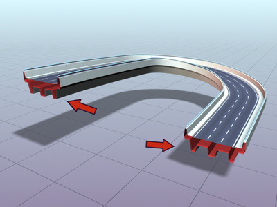
- Contour
-
When on, each shape follows the curvature of the path. The positive Z axis of each shape is aligned with the tangent to the
path at the shape's level. When off, shapes remain parallel and have the same orientation as a shape placed at level 0. Default=on.
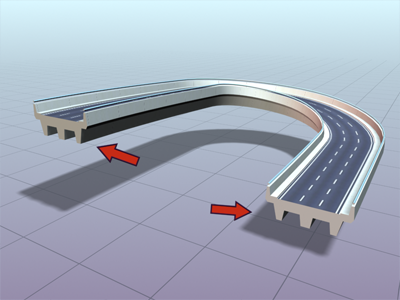
- Banking
-
When on, shapes rotate about the path whenever the path bends and changes height in the path's local Z axis. The bank amount
is controlled by 3ds Max. Banking is ignored if the path is 2D. When off, shapes do not rotate about their Z axis as they traverse a 3D path. Default=on.
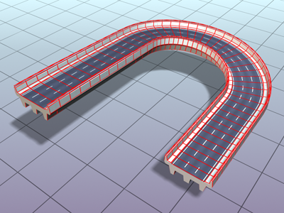
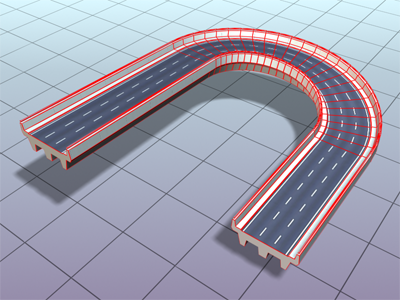
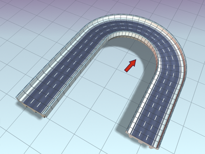
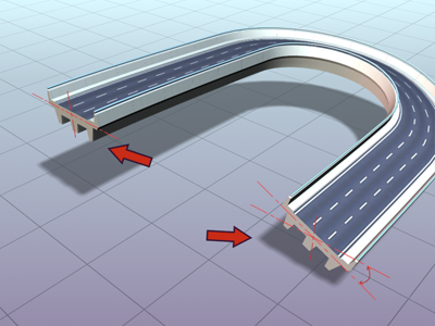
- Constant Cross Section
-
When on, the cross sections are scaled at angles in the path to maintain uniform path width. When off, the cross sections
maintain their original local dimensions, causing pinching at path angles.
- Linear Interpolation
-
When on, generates a loft skin with straight edges between each shape. When off, generates a loft skin with smooth curves
between each shape. Default=off.
- Flip Normals
-
When on, reverses the normals 180 degrees. Use this option to correct objects that are inside-out. Default=off.
- Quad sides
-
When on, and when two sections of a loft object have the same number of sides, the faces that stitch the sections together
are displayed as quads. Sides between sections with different numbers of sides are not affected, and are still connected with
triangles. Default=off.
- Transform Degrade
-
Causes the loft skin to disappear during sub-object shape/path transformations. For example, moving a vertex on the path causes
the loft to disappear. When off, you can see the skin during these Sub-Object transformations. Default=off.
Display group
- Skin
-
When on, displays a loft's skin in all views using any shading level and ignores the Skin In Shaded setting. When off, displays
only the loft sub-objects. Default=on.
- Skin in Shaded
-
When on, displays a loft's skin in shaded views regardless of the Skin setting. When off, skin display is controlled by the
Skin setting. Default=on.
The loft object now retains the Skin and Skin In Shaded settings from one loft object to the next one created.