Chapter 12, Image Processing Tools
| About Image Processing Tools | Formatting Tools | ||
Chapter 12, Image Processing Tools |
|||
You can use Filtering tools to apply a range of looks, feels, and transitions to your composites.
| Tool: | Description: |
| Remove Dust | Removes dust, dirt, hair and scratch artifacts from sequences of images--see Remove Dust Tool. |
| Blur | Applies a blur to an image--see About Blurs. |
| Lens Blur | Accurately simulates the defocus effect of a real camera on an HDR image--see Lens Blur Tool |
| Median | Removes impulse noise with an edge-preserving smoothing filter--see Median Tool. |
| Sharpen | Increases clarity of an image--see Sharpen Tool. |
| Unsharp Mask | Provides more sharpening control of fine detail in an image--see Unsharp Mask. |

Use the Remove Dust tool to remove dust, dirt, hair, and scratch artifacts from sequences of images. Dust removal, encompassing what is sometimes called dust-busting, dust repair, scratch removal and scratch repair, is traditionally a time-consuming task, requiring visual inspection and manual correction steps for each frame of film or video. This tool provides you with a means to automate this task as much as possible, and to easily tweak the results manually. The tool automatically detects dust and scratches, and automatically repairs them. You can view the results of the detection phase and easily correct anything using a simple mouse stroke.
The Remove Dust tool detects dust in images and removes the dust from the images. The tool has a primary color image input and outputs two images, the repaired color image and a mono-channel defect matte. An optional second input can be used to specify the defect matte as a mono-channel image, and any dust detected by the tool is added to the dust supplied by the defect matte. If the defect matte input is not present, the tool initializes the defect matte to empty. Optional third and fourth inputs supply forward and/or backward motion vectors to the tool which it can use for the detection and/or the correction phase.

 "Show full-size image")
The dust removal workflow can be divided into three steps:
Dust Detection -- This automatically creates the defect matte by examining the images, using motion vectors if available. This step is optional, as the defect matte may be supplied to the tool as the second input. Even if no defect matte is supplied, you may choose to bypass detection and perform all labeling by hand. A single tolerance parameter controls the dust detection, where a value of 0 means no dust is detected, and a value of 100 means all pixels are dust. You can tweak the value slightly from its default of 50 to get a reasonable set of dust pixels. Two other parameters control the expansion of the dust to make sure the whole dust object is covered, not just the center.
Manual correction of the defect matte -- If any pixels have been incorrectly labeled as dust or not dust in step 1, manual correction of the defect matte can be performed by drawing appropriate shapes on the dust matte. These locally change the detection and repair parameters within the geometric region of the shape. Each object drawn has its own dust detection parameters, which overrides the global (automatic) values used in step 1. In addition, each object has other parameters to control how correction is performed. Of course, drawing shapes is optional.
Defect repair -- Using the final defect matte, an image processing operation is performed to fill in the corresponding pixels in the output image with corrected pixels. This process uses motion vectors if they are available. Your can choose between a spatial repair, which uses only the current frame, or a temporal repair, the default, which uses neighboring frames and motion vectors. Spatial repair should only be used in areas of the image where the motion vectors are inaccurate or there are occlusions making it difficult for the algorithm to find the corresponding correct pixel on neighboring frames.
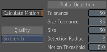
The Global Detection UI has the following parameter controls:
 "Show full-size image")
| Use: | To: |
| Calculate Motion | calculate forward and backward motion vectors. |
| Quality | control the quality of the motion vectors by applying the motion analysis only to lower-resolution versions of the input image, up to the resolution specified by the quality parameter. |
| Tolerance | determine how many pixels are classified as dust. If the Tolerance is set to 0, then no dust is detected, effectively disabling the dust detection. If a dust channel from a film scanner is applied, the Tolerance can be set to 0 to avoid dust detection. Otherwise, the dust channel will be the union of the scanner matte and the detected matte. If the Tolerance is set to 100, then all pixels are dust. A value of 100 might be used with a shape to label all pixels within a small region as dust. |
| Size Tolerance | control into which regions the dust is expanded. A value less than or equal to Tolerance means do not expand |
| Size | control how expanded the detected dust is expanded. A value of 0 means do not expand. |
| Detection Radius | control the smoothing effect on the first step of dust detection where every pixel is assigned a likelihood of being dust. |
| Motion Threshold | remove false dust in areas of motion, as its value is raised. |
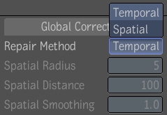
The Global Correction UI has the following parameter controls:
 "Show full-size image")
| Use: | To: |
| Repair Method | select either the Temporal or Spatial repair method. The default method is temporal repair. This means to replace a dust pixel with the average of the corresponding pixels in the previous 2 and next 2 frames. If motion vectors are supplied on the 3rd or 4th input, they will be used to define the correspondence; otherwise, the corresponding pixel on another frame is just the pixel at the same position as the dust pixel. Spatial repair is used in areas where the motion vectors are incorrect or the previous and next frames do not contain the corresponding pixel needed (due to occlusion or intensity changes). In this case, the dust is filled using texture infilling and copies reasonable pixels from other places within the same frame. Note that there are no parameters for the Temporal repair method. When Temporal repair method is selected, the Radius, Distance and Smoothing parameters will be grayed out. |
| Spatial Radius | set how large a texture patch to use for matching areas around the dust. |
| Spatial Distance | set how far to search from the dust to find a pixel to put in place of the dust. |
| Spatial Smoothing | set how smooth to make the infilling of the dust. |
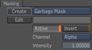
Occasionally there will be parts of the image where some of the Global (automatic) parameters need to be changed locally to improve the dust detection and repair. For this, you can use a shape drawing facility based on the Garbage Mask tool. The UI is very similar to the Garbage Mask but does not have the mask list user settings or edge gradients, however all Garbage Mask hot keys affecting control points are the same--see Chapter 18, Masking. The objects that are drawn are non-animated and appear only on one frame of the composition. You can select and edit the objects only by direct manipulation on the image wireframe overlays.

 "Show full-size image")
When in creation mode (either Rectangle, Ellipse, or Spline is selected) you can set the Detection and Correction values that will apply only within the shape to be drawn. When in selection mode (either Select or Transform), the UI looks the same as in creation mode, except that the values are for the currently selected shape. The two garbage can buttons provide deletion of selected shapes, and all shapes on the current time frame, respectively.
Each drawn shape has several values associated with it, the first 3 of which override the corresponding global (automatic) parameter in the area of the shape:
| Use: | To: |
| Tolerance | override the global detection tolerance. |
| Size Tolerance | override the global size tolerance. |
| Size | override the global dust expansion amount. |
| Repair Method | override the global repair method. The default is Temporal. You would only switch to Spatial Repair in areas where the motion is so complicated that the motion vectors are incorrect. Note that there are no parameters for the Temporal repair method. When Temporal repair method is selected, the Radius, Distance and Smoothing parameters will be grayed out. |
| Spatial Radius | set how large a texture patch to use for matching areas around the dust. |
| Spatial Distance | set how far to search from the dust to find a pixel to put in place of the dust. |
| Spatial Smoothing | set how smooth to make the infilling of the dust. |

 "Show full-size image")
|
|
|
The defect matte is output on the second output, thus allowing the use of context points--see Setting Context Points to view the input defect matte and the defect matte after dust detection has been applied. You can get the second output node from the Utilities folder in the Tools tab.
Use the Blur tool to finish shots that require directional, radial, modulated, and vectors blurs. This includes shots that require some amount of depth of field or motion blurs. In modulated blurs, you can vary the amount of blur from pixel to pixel. The ability to vary the amount of blur applied at each pixel is sometime useful to model specific physical processes or be used for purely artistic goals.
The Blur tool UI is composed of five tabs:

 "Show full-size image")
| Tab | Controls |
| Blur | Settings for the directional Gaussian blur and the Radial blur--see Directional Gaussian and Radial Blur. |
| Modulation | Settings for the Modulated blur--see Modulation Blur. |
| Vectors | Settings for the Vectors blur--see Vectors Blur. |
| Output | Settings affecting the image output by the tool--see Output Controls. |
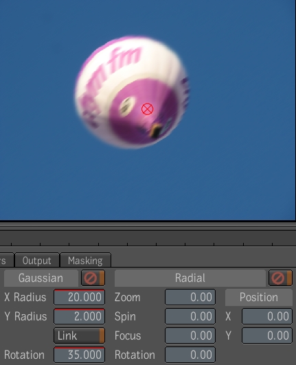
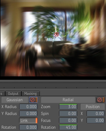
The Directional Gaussian blur filter lets you scale and rotate its elliptical shape. This allows you to blur an image by a certain amount in a given direction, and by a different amount in a direction perpendicular to it. Each pixel is blurred by the same amount.

 "Show full-size image")
 "Show full-size image")
| Use: | To: |
| X Radius | Set the amount of blur to apply in direction of the X axis (before taking into account the rotation parameter). |
| Y Radius | Set the amount of blur to apply in direction of the Y axis (before taking into account the rotation parameter). |
| Link | Couple the X Radius and Y Radius so that when you change the X Radius or the Y Radius the other changes in the same proportion. |
| Rotation | Rotate the X and Y axis of the Gaussian by a given angle. The angle is specified in degrees. |
| Mute | Mute the Directional Gaussian Blur contribution of the Blur tool. The other blurs are still applied (if not also muted). |
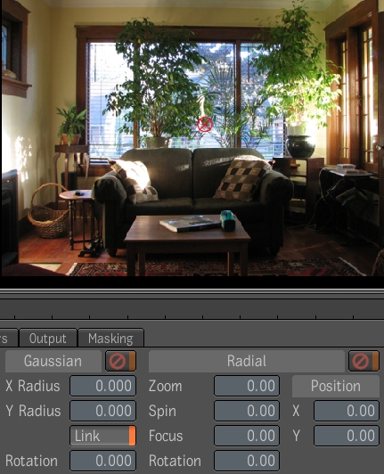
The Radial Blur simulates the effect of motion blur that would be generated by the movement of the camera due to zooming and spinning around a given point. The zooming and spinning movements are simply converted into motion vectors representing the local displacement at each pixel. These motion vectors are then used to construct blur ellipses aligned with each vector. The size of the major axis matches the length of the displacement vector. The size of the minor axis is kept fixed at a small value. That value is chosen to keep aliasing artifacts at an acceptable level while not introducing too much blurriness.
 "Show full-size image")
 "Show full-size image")
| Use: | To: |
| Zoom | Set the amount of blur to apply in the radial direction (before taking into account the rotation parameter). The amount of blur is specified in degrees; the further a pixel is located from the center of the radial blur, the more it is blurred. Expressing the Zoom parameter in degrees allows it to share the same units as the Spin parameter. This lets you express a given amount of blur in either the radial or the tangential direction. |
| Spin | Set the amount of blur to apply in the tangential direction (before taking into account the rotation parameter.) The amount of blur is specified in degrees; the further a pixel is located from the center of the radial blur, the more it is blurred. |
| Focus | Controls how the strength of the blur relates to distance from the center of the effect. Increasing the amount of focus keeps the center of the effect in focus at the expense of the outer rim. With a Focus value of zero, the strength of the blur increases linearly with distance from the center. |
| Rotation | Rotate the radial and tangential direction by a given angle. The angle is specified in degrees. This causes the blur effect to spiral. |
| X,Y Position | Specify the center of the radial blur. You can also click and drag the red manipulator in the player to set the location of the center of the blur. |
| Mute | Mute the radial blur contribution of the Blur tool. The other blurs are still applied (if not muted then themselves). |
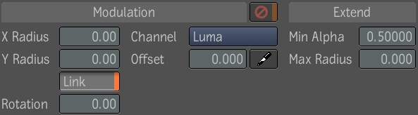
A particular color channel (red, green, blue, alpha or luminance) of the modulation input image can be used to modulate a modulated motion blur. The end effect is that the modulation image will apply a varying amount of scaling at each pixel. The elliptical shape of the blur filter is scaled uniformly by this modulation amount.
The Modulation blur tool has the following parameters:
 "Show full-size image")
| Use: | To: |
| X Radius | Set the amount of blur to apply in direction of the X axis (before taking into account the rotation parameter). |
| Y Radius | Set the amount of blur to apply in direction of the Y axis (before taking into account the rotation parameter). |
| Link | When enabled, changing the X Radius or the Y Radius causes the other one to change in the same proportion. |
| Rotation | Rotate the X and Y axis of the Gaussian by a given angle. The angle is specified in degrees. |
| Channel | To specify which channel of the "Modulation Image" is used to control the modulated blur. The valid channels are: Red, Green, Blue, Alpha, Luma and None. When None is selected, the image is blurred as if the Modulation Channel had a constant value of 1. Note that this behavior is different than muting the entire modulated blur. This is an aid for trying to figure out what the various parts of the tool contribute. |
| Offset | To offset the selected modulation channel before it affects the modulated blur. The offset is subtracted from the channel. The output image will be in focus where the modulation channel is equal to the modulation offset; it will be progressively blurrier for values of the modulation channel above and below the modulation image. When the modulation tab is displayed and the Player is in Display Tool output mode, selecting the offset picker tool then clicking anywhere in the player will set the Offset parameter to the value of the selected modulation channel under the pointer. This is useful for selecting the in-focus object in a scene. |

 "Show full-size image")
| View from top showing relative positions of objects in the scene. |

 "Show full-size image")
| Image with no modulated blur. |

 "Show full-size image")
| Z Depth modulation image - closer objects appear as lighter shades of gray; farther objects appear darker. |
 "Show full-size image")
| Luma channel offset value of sphere is 0.011 and matches that of the modulation image retaining focus. |

 "Show full-size image")
| Luma channel offset value of column is 0.704 and matches that of the modulation image retaining focus. |
Although the Modulation Blur tool can simulate depth of field, artifacts may appear for a number of reasons and are inherent 2.5D motion blur and depth of field.
Depth of field is a process that occurs in 3D. Out-of-focus objects blur on top of objects that stand further away. They never blur on top of objects in front of them. The modulated blur does not make this distinction about objects that are in front or behind thus causing artifacts every time a silhouette edge appears in an image. Rendering depth of field therefore requires segmentation of the image along the silhouette edges. Please note that it is not always possible to partition a scene into separate objects using silhouette edges.
Anti-aliased images also cause some problems in that the Z-channel cannot be used to determine which portion of the pixel belongs to the background object and which part belongs to the foreground. When an object becomes out of focus, one starts to see parts of the scene that were not visible before through the blurred edge. To replicate that effect as a 2D post-process, the depth of field tool must guess what the background pixels might look behind foreground objects. To do this, segmenting and matting out foreground objects' then reconstructing the background using in-filling techniques become necessary and which can be a difficult task.
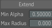
To correct some of the Z-channel problems, the 3D elements of a scene can be rendered as separate layers. The scene would be manually segmented into objects all having approximately the same Z. A single layer would not have any significant Z discontinuities. Each layer can be properly anti-aliased. The Z-information of the foreground element and the background element would be available at partially covered edge pixels and the color of the background objects behind foreground elements would also be available. However, the Z-information is not defined at the transparent pixels of each layer. A renderer is likely to assign them some very far-away value. To the modulated blur tool, this represents a huge discontinuity in its blur modulation and the Z-discontinuity ends up as a discontinuity in the blurred image. To help remove the resulting artifacts, the parameters (Min. Alpha and Max Radius) under the Extend label can be set to generate the missing Z information.
 "Show full-size image")
| Use: | To: |
| Min Alpha | Select at which alpha value to start generating the missing modulation values. Anything opaque is unaffected up to the Min. Alpha value. |
| Max Radius | Increase the radius (in pixels) of the modulation value generation. Increase this value until the artifacts are removed. Note that increasing the Max Radius value beyond the point where the artifacts are removed will result in slower processing. |
Use the Vector Blur tool to specify the length and the width of the blur ellipses. The blur ellipses are then oriented independently for each pixel in the direction of the vectors of the Forward Vector input image and uniformly scaled by the length of the vectors. You can also apply an extra constant rotation to all the blur ellipses.
Using this definition of vector blurs you can blur only in the direction of the vector field. To do this, set the amount of blur in the perpendicular vector direction to zero. No matter how much it is scaled, it will always stay null. Then, use the minimum blur radius control to clamp to a finite value to avoid sampling aliasing.
Note: If the ROD of the Forward Vectors image is smaller than the ROD of the image produced by the Blur tool, the pixels lying at the edge of the Forward Vectors image are repeated to cover the missing region.
The Vectors blur tool has the following parameters:
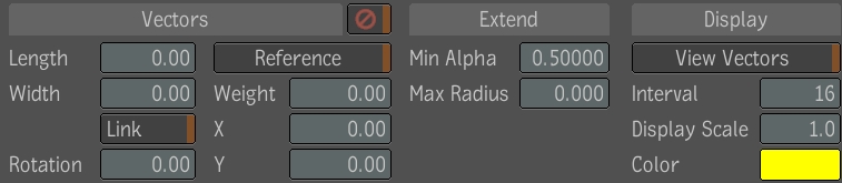
 "Show full-size image")
| Use: | To: |
| Length | Set the amount of blur to apply in direction of the forward vectors (before taking into account the rotation parameter). The amount of blur applied per pixel is also modulated by the length of the vectors. |
| Width | Set the amount of blur to apply in a direction perpendicular to the forward vectors (before taking into account the rotation parameter.) The amount of blur applied per pixel is also modulated by the length of the vectors. It would often be left at 0, so that the vector length would not affect it. |
| Link | When enabled, changing the Length or Width parameter causes the other one to change in the same proportion. |
| Rotation | Set the amount of vector rotation around their own origin. |
| Reference | Enable the reference vector offset. If reference is set, the vector at the Reference Position is subtracted from all forwards vectors in the image. The result is that the pixel at the reference position will not be blurred, and so will pixels with similar forward vectors. |
| Weight | Set the amount of blur to apply at the reference position. A value of zero means that no blur should be applied. This is the default. A value of one means to blur by the same amount as the forward vectors at the Reference Position. This is equivalent to disabling the use of a reference vector offset. A value of one half means to blur half as much as the forward vectors at the Reference Position. |
| Reference Position X and Y | Set the nominal coordinates of the reference position. When the reference is enabled, a manipulator is displayed in the player to allow the user to interactively set the reference position by simply dragging the manipulator (click-drag-release). The reference position can also be set using the Tracker. |
| Mute | Mute the Vector Blur contribution of the Blur tool. The other blurs are still applied (if they are not themselves muted). |
Using the Modulation blur tool to simulate motion blur can be difficult due to some of the same inherent issues as when trying to simulate depth of field using the Modulation blur tool;
Need to segment out at silhouette edges.
Can not deal with anti-aliased images at silhouette edges.
Needs the background pixels behind foreground elements.
Discontinuity in the motion vector field ends-up as discontinuity in the blurred image.
Needs to out-fill motion vectors over transparent region.
These limitations can be worked around, if the 3D department has already partitioned the image into layers of constant movement. You can then use the Min. Alpha and Max Radius parameters of the Vectors blur tool to extend the motion vectors field to get more realistic motion blur effects.
| Use: | To: |
| Min Alpha | Select at which alpha value to start generating the missing vector information. |
| Max Radius | Increase the radius (in pixels) of the vector field generation. Increase this value until the artifacts are removed. Note that increasing the Max Radius value beyond the point where the artifacts are removed will result in slower processing. |
| View Vectors | Toggle the vector view. |
| Interval | Set the interval between shown vectors. By default, this value is 16 (i.e. show a vector every 16 pixels). This controls the density of the displayed vectors. |
| Display Scale | Set the display Scale of the shown vectors. By default, this value is 1.0 (i.e. show a vector with its original length). This controls the displayed length of the vectors,. These values only control the player display. They have no influence on processing. |
| Color | Set the color of displayed vectors. Click on the color pot to display the color picker--see Color Picker. |
Note: The Blur tool has a masking input--see Pixel Masking. The Blur tool's X and Y attributes are both animatable by setting keyframes or using expressions--see Setting Keys Manually and Validating and Applying the Expression String.
The Output UI allows you to control the following parameters:
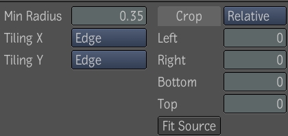
 "Show full-size image")
| Use: | To: |
| Min Radius | Specify a minimum of blur to apply in any direction. This is useful to minimize aliasing artifacts that might occur when performing blurs that exhibits a high degree of directionality. |
| Tiling X and Y | Specify how the input image should be extended outside its region of definition (ROD). This is important for two reasons. First, the convolution kernel of the Blur tool might need to access source pixels outside the ROD to produce pixel falling inside the source ROD. Secondly, the Blur tool allows the output image to be uncropped arbitrarily. The supported tiling modes are Edge (default), Transparent, Repeat, and Mirror. |
| Crop | Crop (and uncrop) the image produced by the Blur tool. The cropping controls works exactly like the ones found in the Crop tool with the exception of the addition of an Auto Crop mode. When in Auto Crop mode, the Left, Right, Bottom and Top controls are greyed out. Instead the output ROD is computed automatically based on the following assumptions; only the parameters of the Gaussian Blur are used to determine the output ROD. This includes the Gaussian X radius, Y radius and Rotation; the Input ROD is enlarged by an amount proportional to the rotated" X and Y radius. It is enlarged sufficiently so that the profile of the Gaussian filter drops sufficiently close to zero at the boundary of the enlarged kernel. This behavior is especially useful when the X and Y Tilling modes are set to Transparent. The supported crop modes are Relative (default), Window, Absolute, and Auto Crop. |
The Lens Blur tool let you simulate rack defocus and add photographic effects to 3D rendered scenes or live footage. You can also create lens flares, streak lines, and halos around bright lights and reflections.
The Lens Blur UI is composed of four tabs: Lens Blur, Modulation, Output, and Masking.

 "Show full-size image")
The Lens Blur tab consists of a set of parameters for setting the main blur effect, as well as controls to create bloom, flares, and halos.
To create the main blur effect, use the controls on the left side of the UI.

 "Show full-size image")
| Use: | To: |
| X Radius | Set the amount of blur to apply in the direction of the X axis. |
| Y Radius | Set the amount of blur to apply in the direction of the Y axis. |
| Link | When enabled, changing the X Radius or the Y Radius causes the other one to change in the same proportion. |
| Aberration | Set the aberration. Setting the aberration parameter to greater than 0 will make the radius different for each of the three color planes, introducing color fringes. |
| Radial Aberration | Set the radial aberration. Setting the radial aberration greater than 0 will scale the image about the center differently for each color plane, producing color fringes that are offset radially, simulating transverse aberration. |
| Aperture Shape | Select either regular polygon shapes or ellipses. |
| Number Sides | Set the number of sides of the polygon blur shape. |
| Rotation | Set the rotation of the shape (in degrees). |
| Softness | Extend the blur outward from the edge of the polygon with an exponential falloff curve. Softness is specified as a distance (the same as the radius). |
| Antialias | Turn on and off the higher quality rendering of the polygon/ellipse blur. |
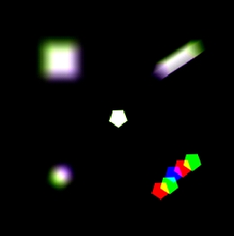
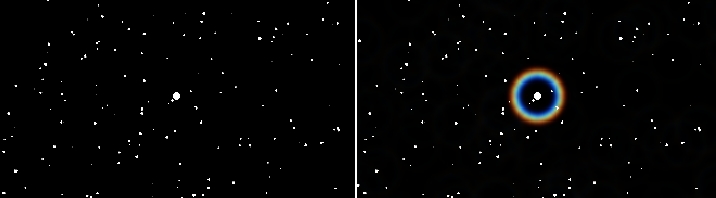
The following images show the types of effects you can generate using the main blur controls.
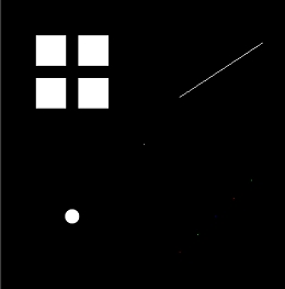
 "Show full-size image")
| Input image (some single pixels not visible) |
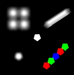
 "Show full-size image")
| Pentagon blur with softness set at 2 pixels |

 "Show full-size image")
| Pentagon blur with softness set to 20 pixels |

 "Show full-size image")
| Pentagon blur with aberration |
 "Show full-size image")
| Radial chromatic aberration |

 "Show full-size image")
The Bloom controls let you remap the higher luminance range to increase the bloom appearance of the blur. This is especially useful for 8-bit images which cannot represent values greater than 1. With bloom, you can remap the values to make it seem like an HDR image, giving you more realistic blooms around bright light sources and reflections.
 "Show full-size image")
| Original image | Bloom added |
 "Show full-size image")
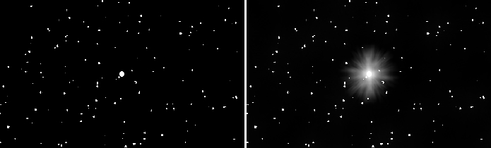
The Flares parameters let you add lines and streaks emanating from bright lights and reflections. You can set the intensity of the flares, as well as the number of flares. An intensity of 0 (the default) will disable flare generation. The rotation of the lines can be animated to simulate flares that seem to rotate as the camera moves relative to the light sources. The Randomness parameter controls how evenly distributed the lines are. A value of 0 makes the flare lines uniformly distributed around a circle, while a value of 1 makes them completely randomly distributed. You can also set a seed value to choose a particular sequence of lines. The effect of adding flares will be somewhat like the linear patterns in the right image below.
 "Show full-size image")
| Original image | Flare lines added |

 "Show full-size image")
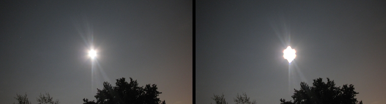
The halo is a ring of brightness of a specified radius from the center of bright lights, and with a specified width. If the radii differ among the color channels, the effect is a rainbow halo like in the following right image. This is controlled by the Aberration parameter. There is also an intensity parameter to adjust the strength of the halo; the default value of 0 disables the halo creation.
The Grating is a set of lines of random intensity, uniformly distributed around the circle. Increasing the Grating Density parameter increases the number of lines, and the smoother it appears.
 "Show full-size image")
| Original image | Halo added |

 "Show full-size image")
The Modulation tab looks just like that of the Blur, including the extrapolation (extending) capability--see Modulation Blur. You can choose what channel of the modulation image is used and apply an offset to the modulation image. The modulation can affect the X and Y radius, or the rotation of the polygonal or ellipse shape.

 "Show full-size image")
The Output tab is the same as that of the Blur tool, but without the Min Radius parameter--see Output Controls.
 "Show full-size image")
The Lens Blur tool has a masking input and a Masking tab--see Pixel Masking.
The Median tool is an edge-preserving smoothing filter that works particularly well for removing impulse noise.
For grayscale images, the median filter works by ranking the pixels under the kernel according to their value and selecting the median to replace the pixel at the center of the kernel. This approach effectively removes spikes in the original image without the blurring typically introduced by common smoothing kernels (e.g. Gaussian).
For color images, there is no single concept of ranking, so several different criteria are supported. Component-wise ranking computes the median of each color component independently, however, this can result in pixel colors that did not belong in the original image. Luminance ranking computes the median of the luminance of each pixel under the kernel. This approach is fast and does not introduce new colors in the original image, however, luminance is not the best criteria for similarity in a color image. RGB Vector does not really rank the pixels under the kernel, but rather it chooses as the median the one pixel with the smallest sum of square distances (in RGB space) to all the other ones under the kernel. It selects the pixel that is closest to the center of the point cloud obtained by looking at the pixels under the kernel as points in 3D space. This approach is computationally intensive, but can yield better results than either of the other ranking criteria.
The median filter uses a square neighborhood and can round the corners of axes-aligned rectangular objects in an image.
As any noise reduction filter, the median filter may also affect the sharpness of small details in the input image. When this problem arises, the result of the median filter can be blended with the original image to decrease its effect.
Finally, the median filter can be applied recursively. Repeated applications using a small kernel size yield better results than a single application using a large kernel.
Note: When using the filter recursively, the blending described above is applied at each iteration.
The Median tool has the following parameters:

 "Show full-size image")
| Use: | To: |
| Filter | Control the choice of filter used:
|
| Size | Control the size of the filter:
|
| Criteria | Control how the median value is chosen:
|
| Blend | Control how the result of one median iteration is combined with the original input. This parameter can vary between 0 and 100% (default). |
| Iterations | Control the number of times that the filter is applied recursively. This parameter can vary between 1(default) and 9. |
The Sharpen tool lets you increase the clarity and focus of an image. The Sharpen tool applies a sharpening filter to a number of adjacent pixels in the input image and increases their contrast.
Drag the Sharpen tool from the Tool tab to the dependency graph in the Schematic view.

 "Show full-size image")
Adjust the sharpen amount by dragging the value slider, or by typing in a value.

 "Show full-size image")
Note: The Blur tool has a masking input--see Pixel Masking. The Sharpen tool's Amount value is animatable by setting keyframes or using expressions--see Setting Keys Manually and Validating and Applying the Expression String.
The Unsharp Mask tool lets you sharpen the edges and other fine details in the input image.
Unsharp masking provides more control on the sharpening process and will generally produce better results than the Laplacian filter, but at a higher computational cost.
Unsharp masking works by removing the low frequency spatial information from the image and emphasizing the high frequency details. The algorithm basically uses a Gaussian filter to produce a smooth version of the original image, called unsharp mask. The unsharp mask is then subtracted from the original image, removing low frequencies.
The Unsharp Mask tool has the following parameters:

 "Show full-size image")
Unsharp Mask Radius X, Radius Y, and Link -- Control the radius of the blur (just like in the Blur tool). By default, the X and Y radii are linked and set to 1.20; otherwise, their range is the same as that of the Blur tool.
Strength -- Controls the strength of the effect of masking that is added. Basically, the output image is computed as I+s*(I-M) where I is the original image, M is the unsharp mask, and s is the strength parameter (in 0 to 500 percent; default 100%).
Threshold -- Defines how large the difference between the original image and unsharp mask must be before the original pixels are changed. A pixel is changed if the difference in any of its components is larger than or equal to the threshold (in 0 to 100%; default is 0%).
Note: This tool can either affect the RGB components or the Alpha component, but not both at the same time.
