In the Wipe Editor and Garbage Mask, you add nodes to the schematic from the Node box. You use Axis and Geom nodes to create wipes and garbage masks.
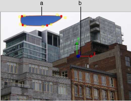
In these schematics, Axis nodes control the position, rotation, and scaling of masks. Geom nodes contain information about how the mask affects the image (softness, opacity, alpha, shape, and axis offset).
In Action, Batch, and the Modular Keyer, you add a node to the schematic from a node bin. In the Batch and the Modular Keyer flow graph schematics, nodes represent an effect or process. In the Action scene-based schematic, nodes represent the type of object you can add to a scene. Refer to the following for information on how to add nodes from the node bin:
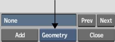
To add a node from the Node box:


| Select: | In: | To add: |
|---|---|---|
| Axis | Wipe Editor or Garbage Mask schematic | An Axis node. |
| Geometry | Wipe Editor or Garbage Mask schematic | A Geometry node parented by an Axis node. |
The object is added to the scene and a node representing the object is added to the schematic.
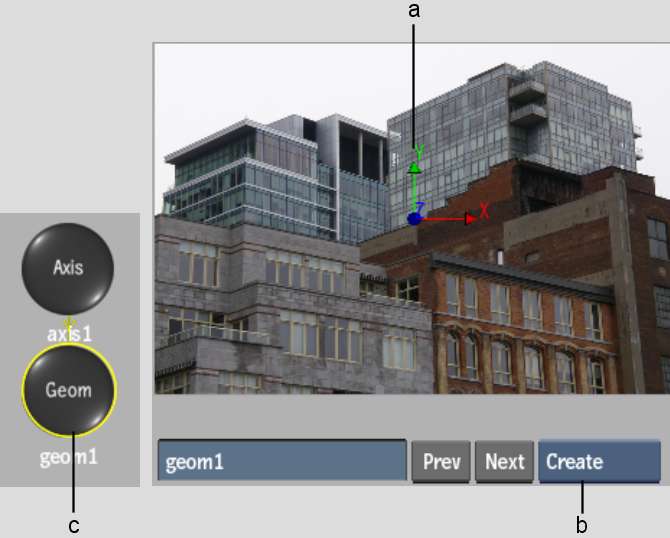
When a Geometry node is added to the schematic, an Axis node is also added and the Geometry node is automatically linked to the Axis node.
As well, adding a Geometry node automatically activates Create mode (for drawing masks).
In the following example, a Geometry node is added to the Garbage Mask schematic.


(a) Axis in scene corresponds to Axis node in schematic (b) Create mode for drawing mask (c) Geometry node is automatically linked to Axis node


(a) Geometry node controls how the mask affects the image (b) Axis node controls the position and size of the mask