The Surface menu includes properties common to all surfaces, and specific controls for bilinear and bicubic surfaces. You can change a surface's shape, position, and transparency, as well as apply lighting effects. You can also apply four-point tracking data to a bilinear surface.
The Object Image menu appears with the Image controls for the selected surface displayed on the right side of the menu.


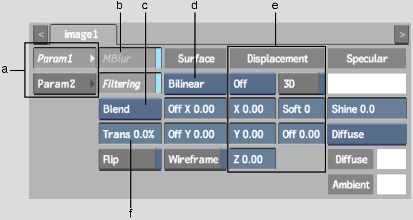
(a) Parameter tabs (b) Motion Blur button (c) Blend Mode box (d) Shape box (e) Displacement controls (f) Transparency field
The following surface controls are common to all types of surfaces.
Parameter tabsDepending on what type of surface is selected in the Shape box, there may be extra controls in the parameter tabs.
MBlur buttonRemoves the blur for the selected surface, excluding it from the global motion blur. This option can only be used when the global motion blur is enabled.
Shape boxSets the shape of the surface. See Changing the Shape of a Surface
Blend Mode boxSets surface blending mode. See Surface Blending Modes.
Filtering buttonEnables or disables bilinear filtering. See Filtering.
Transparency fieldBy adjusting the transparency of the surface, you can make it fade in or out of view, or simulate a transparent material, such as glass. When the Trans field is set to 100, the surface is completely transparent. When the value is set to 0, there is no transparency in the surface.
Displacement controlsCreates a 3D model using a 2D surface. See Adding a Displacement Map.
Specular Highlight colour potSet the highlights of a surface. Click the colour pot to select the colour of the surface highlights. See Adjusting Specular Highlights.
Shine fieldAdds a shine to the specular highlights. There are no specular highlights when Shine is set to 0.
Lighting boxSets Ambient or Diffuse lighting so that the surface can reflect incidental light. See Applying Incidental Light Reflection.
Flip buttonFlips the selected surface normals. This button is used to light the back side of a surface, and has no incidence on the media or the orientation of the image that is displayed by the surface.
Wireframe buttonConverts the selected surface to a wireframe representation. Lighting and transparency properties are kept.
Surface Offset fieldsOffsets a surface along the X-axis or Y-axis. See Offsetting a Surface.
For bilinear surfaces, there are extra controls available in the Param2 tab.
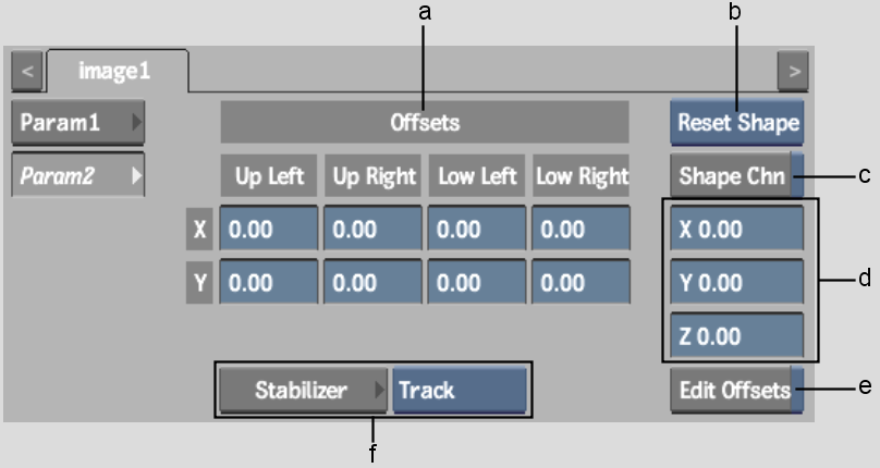
(a) Offsets fields (b) Reset Selection box (c) Shape Channel button (d) Vertex Translation fields (e) Edit Offsets button (f) Stabilizer controls
Edit Offsets button and Offsets fieldsEdits tracker offsets. See Editing Tracker Offsets of a Bilinear Surface.
Reset Selection boxSelect Reset Shape to reset the surface shape handles to their default position. The handles are reset in the current frame only. If Auto Key is enabled, a shape key is added at the current frame. Select Reset Points to reset selected points on the surface.
Shape Channel buttonSpecifies whether you want to use the Shape channel or Surface vertex channels in the Channel Editor. See Reshaping Using the Channel Editor.
Vertex Translation fieldsVerifies the coordinates of the currently selected vertex or tangent. You can modify these values to alter the shape of a surface. Press Ctrl and click the field to reset the selected vertex to its original position. See Changing the Shape of a Surface.
Stabilizer controlsUse to apply stabilizing data to a surface or surface offsets.
For bicubic and extended bicubic surfaces, there are extra controls available in the Param2 tab.
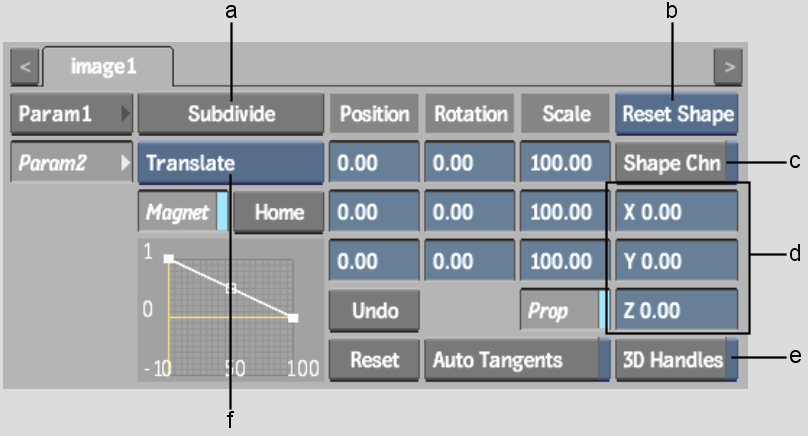
(a) Subdivide button (b) Reset Selection box (c) Shape Channel button (d) Reference Point fields (e) 3D Handles button (f) Magnet Transformation box
Subdivide buttonSubdivides an extended bicubic surface into more sections. See Subdividing an Extended Bicubic.
Position X, Y, Z fieldsMove selected surface points along the X,Y or Z-axis. Hold down Ctrl and select surface points to position them.
Rotation X, Y, Z fieldsRotate selected surface points along the X,Y, or Z-axis. Hold down Ctrl and select surface points to rotate them.
Scale X, Y, Z fields and Prop buttonScale selected surface points along the X,Y, or Z-axis. Hold down Ctrl and select surface points to scale them. Enable Prop to scale surface points proportionally.
Reference Point X, Y, Z fieldsSet the location of the reference point. Use the reference point to constrain the rotation and scaling of an individual or group of vertices.
By default, the reference point appears in the centre of the extended bicubic. When unselected, the reference point is green.
3D Handles buttonEnables Z buffering of the vertices. By default, the vertices are always visible, regardless of their position in Z space in relation to other media.
Auto Tangents buttonScales adjacent tangents automatically. Auto Tangent creates a smooth curve between points in the deformation. If you want to work on a specific area of the image without affecting other tangents, disable Auto Tangents.
Magnet buttonTransforms selected vertices and tangents numerically. Use in conjunction with the Magnet Transformation box. See Transforming Multiple Points.
Magnet Transformation boxDisplays the type of transformation to use when Magnet is enabled.


