Use displacement mapping to create a 3D model from a 2D surface. The values of a selected colour channel in the displacement source clip are used to create a displacement map. When the displacement map is applied to the surface, the pixels of the surface are displaced along the positive or negative X, Y, and/or Z axes. By default, the media for the selected surface is used as the displacement source.
To set the displacement for the selected surface, use the Surface Image menu. To access the Surface Image menu, double-click the surface in the schematic, or follow the tab population rules for the Object menu (see Selecting Objects and Populating Menu Tabs).


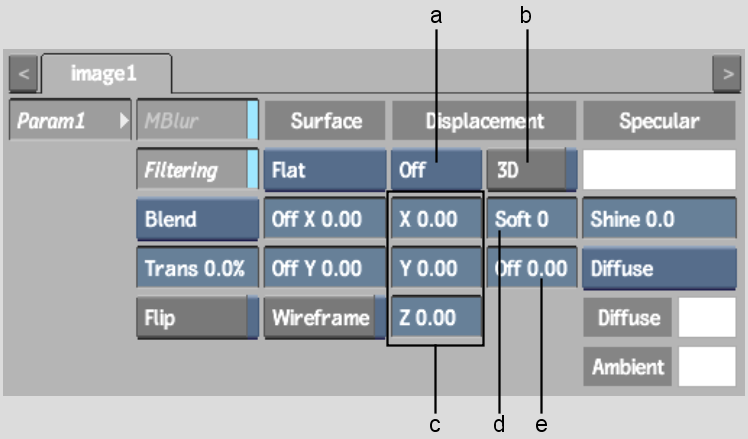
(a) Displacement Channel box (b) 3D Displacement button (c) Displacement axes (d) Displacement Softness field (e) Offset field
The Surface Image displacement controls are described as follows.
Displacement Channel boxCalculates the displacement map by selecting any of the colour channels: Use R, Use G, Use B, Use Y, Use U, or Use V.
Displacement axesSpecifies the amount of displacement in pixel units along the X, Y, and Z axes. Use positive values for displacement on the positive axis, and negative values for displacement on the negative axis.
3D Displacement buttonDisplaces bilinear and bicubic surfaces according to their normals. For image surfaces, disable 3D to displace in the X, Y, and Z directions.
Displacement Softness fieldRounds off, or softens, the spikes that result from colour values in the image that vary from pixel to pixel in the displacement map.
Softness rounds the edges of the displacement. The larger the softness, the smoother the displacement. Softness also affects rendering; the larger the softness, the longer it takes to render.
Offset fieldApplies an offset to the displacement of X and Y.
Using a high-resolution value results in an inaccurate displacement. A low value yields good results, but takes longer to process. Typically, you compromise by specifying a high enough resolution while adding softness to make the rough edges smooth.
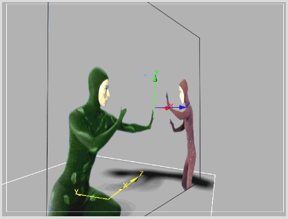
The following figure illustrates a possible use of displacement mapping and shows the difference between displacing with and without softness.
Original image |
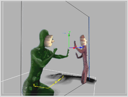
Z-axis displacement (60) using the luminance channel (Y) and a softness of 0 |
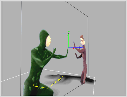
Z displacement (60) using the luminance channel (Y) and a softness of 12 |