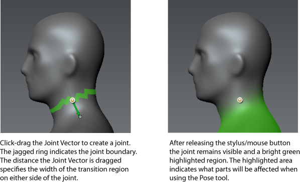
You can pose or deform your models in Mudbox using joints. A joint is a user-specified element that you temporarily place on a model to rotate, transform, or position related model components. It becomes the location from which the associated model deformations occur when using the Pose tool.
Joints are critical for deforming and posing your models into a variety of positions and also allow you to make changes to your model’s proportions and scale that would otherwise be difficult using the sculpt tools alone.
When you create a joint on a model, you simultaneously specify its location, its relative influence upon the surrounding vertices of the model, and its default behavior when the affected vertices are translated using the Pose tool. These items can be edited after their initial creation if required using the Weights or Move Pivot tools.
For models created and rigged using other 3D applications, Mudbox can import the model with joints using the FBX file format so that the joints can be re-used for posing, deformation, and sculpting within Mudbox. For more information, see Import using FBX.

Weights Vector - A green vector with an arrow head appears in the direction that you drag to let you initially specify the default size of the transition region on either side of the joint boundary. The transition region controls how large or small the rotation will be in relation to the joint.
Joint Boundary Ring - A jagged green ring or band of faces is highlighted at the joint location around the affected model component to specify the boundary of the weighted region. You adjust its angle in relation to the model by moving the end of the Weights Vector around the joint as you drag it. Depending on your particular requirements for a deformation, you can adjust the joint boundary to appear perpendicular to the model component or at an angle. The angle of the joint boundary affects the default region of influence for the joint so plays a factor in the posing or deformation behavior.

Two items appear after you drag:
Joint - The joint appears centered within the ring of faces in the area you clicked. For example, if you click in the area of a knee on a character, the joint will appear roughly within the center of that volume. You can reposition the pivot for the joint if necessary using the Move Pivot too. For more information, see Adjust a joint’s pivot location.
Weight Color - A bright green color appears on the model to indicate the default region of influence for the joint. That is, the region of the model that will be affected by the joint when it is subsequently posed or deformed using the Pose tool.
The saturation of the weight color on the model indicates the amount of influence that the joint has on those faces when the affected component gets posed or deformed.
For example, when the weight color is fully saturated it indicates that the faces are fully affected by the joint when the component is deformed. When the weight color is less saturated it indicates that the faces are less affected by the joint when the component is deformed using the Pose tool.
How the region of influence surrounding the joint diminishes or falls off with increased distance from the joint depends on the default Falloff setting (See Adjusting tool falloff) which can be quickly set by selecting a preset from the Falloff tray. The falloff curve is used as the guide along the range of influence you specify when dragging the Weights Vector and controls how the weight color is ramped up or down on either side of the joint.
Import models with existing joints
Adjust a joint’s pivot location