Set up the trackers and the survey points


You can use survey points to analyze the results of 3D tracking and to isolate specific frames or points where adjustment may be necessary.

NoteYou can bypass this section of the lesson by opening Elastic_SetUp_Elastics.mmf. This file can be found in the Tutorials/Elastics directory. You can then proceed to Solve and check the tracking results.
  1. Using the Pan and Dolly controls, make sure both the imported 3D object, which represents the shape of the box, and the image plane are clearly visible.

    For example, set up your viewing position and angle similar to the image below.
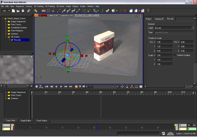
  2. Make sure that the Magnifier window is open by selecting Window > Magnifier Window.
  3. Click-hold the vertex located at the top right corner of the 3D object and move the cursor to the position of the same corner in the image plane.

    As you drag the curser toward the image plane, a red elastic line follows, joining the selected vertex and the image plane.

    Note If you want to abort the operation while dragging the cursor, drag the cursor out of the image plane. The elastic line becomes dashed, meaning nothing will happen when you release the mouse button.
  4. Release the mouse button.

    The elastic is now blue and a new track, Track 01, is created with a point in the current frame (visible in the track view).

    Survey point information issued from the selected vertex is automatically associated to the track. You can see this information in the Parameters window under the Track 01 tab. Click the 3D tab and look in the Survey Info section.

  5. If necessary, you can adjust the position of the tracking point by clicking it in the Magnifier window.
  6. Run forward tracking on the point by pressing F3.

    You can check the quality of the new track by playing the sequence.

  7. Press F2 to play the sequence.

    To get a close-up view of the tracking point, you can lock the sequence play to the Magnifier window. See Supervised 2D tracking.

  8. Go to the first frame and repeat steps 3 to 7 for all the corners of the box.

    Your project should now look similar to the image below.
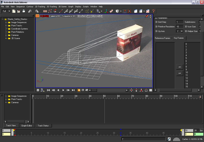
    Note If needed, you can change the viewpoint to better view the 3D object’s vertices and locations on the image plane. You can move and rotate the object in the Workspace by selecting it and using the object manipulator. The transform you apply to the object will not be used in the survey information, unless you specify it by turning on Use Object Transform in the Survey Info section tab of the track Parameters window.

Solve and check the tracking results

To solve and check the tracking results

  1. Select 3D Tracking > Solve For Camera or press F9.

    After the camera completes the solve, blue cones appear at the tracking points on the 3D object and the new tracks appear in the Track window.

    When you look in the Track window, notice that some of your new tracks have yellow segments, indicating that acceptable, but not good tracking. This occurs because the constraints induced by the 3D points are quite strong, while the footage quality does not allow the points to reach a high accuracy on the 2D points locations.

  2. Select View > Lock on Camera.

    The Workspace view now displays the cameras perspective.

  3. Press F2 to play the sequence and check the alignment of the mesh with the image.