The mia_material shading model
The mental ray mia_material is a monolithic material shader that is designed to support most materials used by architectural and product design renderings. It supports most hard-surface materials such as metal, wood and glass. It is especially tuned for fast glossy reflections and refractions (replacing the DGS material) and high-quality glass (replacing the dielectric material).
The major features are:
The material comes in two variants, the original mia_material and the new extended mia_material_x. These are just two different interfaces using the same underlying code, so the functionality is identical, except that mia_material_x ...
This document is divided into sections of Fundamentals (beginning on page Fundamentals) which explain the main features of the material and the Parameters section (page Parameters) that goes through all the parameters one by one, and a Tips Tricks (page Tips and Tricks) with some advice for users.
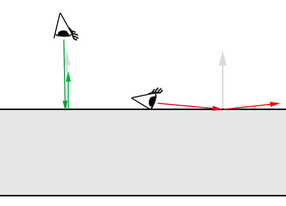
The mia_material primarily attempts to be physically accurate hence it has an output with a high dynamic range. How visually pleasing the material looks depends on how the mapping of colors inside the renderer to colors displayed on the screen is done.
When working with the mia_material it is highly encouraged to make sure one is operating through a tone mapper/exposure control or at the very least are using gamma correction.
Describing all the details about gamma correction is beyond the scope of this document and this is just a brief overview.
The color space of a normal off-the-shelf computer screen is not linear. The color with RGB value 200 200 200 is not twice as bright as a color with RGB value 100 100 100 as one would expect.
This is not a "bug" because due to the fact that our eyes see light in a non linear way, the former color is actually perceived to be about twice as bright as the latter. This makes the color space of a normal computer screen roughly perceptually uniform. This is a good thing, and is actually the main reason 24 bit color (with only 8 bits - 256 discrete levels - for each of the red, green and blue components) looks as good as it does to our eyes.
The problem is that physically correct computer graphics operate in a true linear color space where a value represents actual light energy. If one simply maps the range of colors output to the renderer naively to the 0-255 range of each RGB color component it is incorrect.
The solution is to introduce a mapping of some sort. One of these methods is called gamma correction.
Most computer screens have a gamma of about 2.22, but most software default to a gamma of 1.0, which makes everything (especially mid-tones) look too dark, and light will not "add up" correctly.
Using gamma of 2.2 is the theoretically "correct" value, making the physically linear light inside the renderer appear in a correct linear manner on screen.
However, since the response of photographic film isn't linear either, users have found this "theoretically correct" value looks too "bright" and "washed out", and a very common compromise is to render to a gamma of 1.8, making things look more "photographic", i.e. as if the image had been shot on photographic film and then developed.
Another method to map the physical energies inside the renderer to visually pleasing pixel values is known as tone mapping. This can be done either by rendering to a floating point file format and using external software, or use some plug-in to the renderer to do it on-the-fly.
Two tone mapping shaders are included in the library, the simple mia_exposure_simple and the more advanced mia_exposure_photographic, both of which are documented on page Tone Mapper
Note: Take special care when using tone mapping together with gamma correction; some tone mapping shaders has their own gamma correction feature built in, and if one is not careful one can end up with washed out gamma due to it being applied twice. Make sure to keep an eye on the gamma workflow so it is applied in one place.
The material is designed to be used in a realistic lighting environment, i.e. using full direct and indirect illumination.
In mental ray there are two basic methods to generate indirect light: Final Gathering and Global Illumination. For best results at least one of these methods should be used.
At the very least one should enable Final Gathering, or use Final Gathering combined with Global Illumination (photons) for quality results. Performance tips for using Final Gather and Global Illumination can be found on page Final Gather Performance of this document.
If you are using an environment for your reflections, make sure the same environment (or a blurred copy of it) is used to light the scene through Final Gathering.
Traditional computer graphics light sources live in a cartoon universe where the intensity of the light doesn't change with the distance. The real world doesn't agree with that simplification. Light decays when leaving a light source due to the fact that light rays diverge from their source and the "density" of the light rays change over distance. This decay of a point light source is This decay of a point light source is 1/d², i.e. light intensity , i.e. light intensity is proportional to the inverse of the square of the distance to the source.
One of the reasons for this traditional oversimplification is actually the fact that in the early days of computer graphics tone mapping was not used and problems of colors "blowing out" to white in the most undesirable ways 3 was rampant.
However, as long as only Final Gathering (FG) is used as indirect illumination method, such traditional simplifications still work. Even light sources with no decay still create reasonable renderings! This is because FG is only concerned with the transport of light from one surface to the next, not with the transport of light from the light source to the surface.
It's when working with Global Illumination (GI) (i.e. with photons) the troubles arise.
When GI is enabled, light sources shoot photons. It is imperative for the mia_material (or any other mental ray material) to work properly for the energy of these photons to match the direct light cast by that same light! And since photons model light in a physical manner, decay is "built in".
Hence, when using GI:
Therefore it is important to make sure the light shader and the photon emission shader of the lights work well together.
To solve this, the mia_photometric_light shader (see page Photometric Lights) is included, which automatically balances photons and direct light in the correct way.
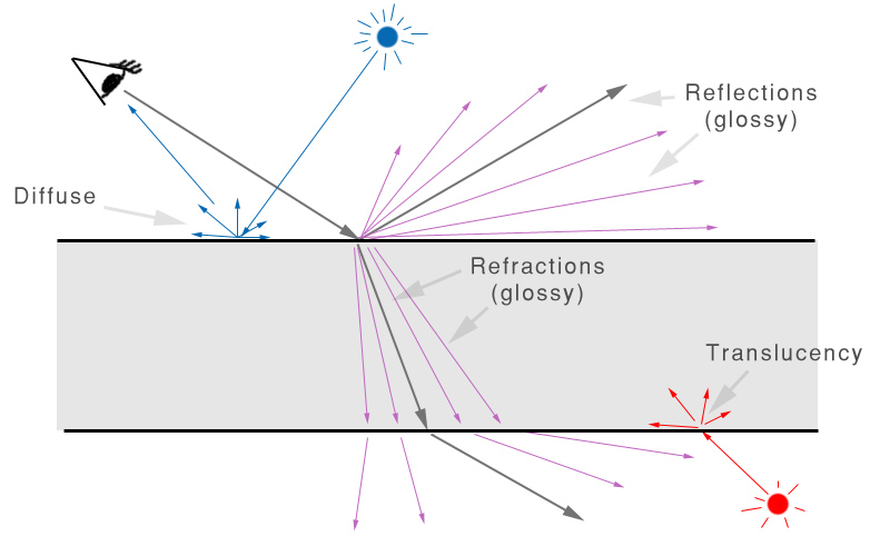
From a usage perspective, the shading model consists of three
components:
Direct and indirect light from the scene both cause diffuse reflections as well as translucency effects. Direct light sources also cause traditional "highlights" (specular highlights).
Ray tracing is used to create reflective and refractive effects, and advanced importance-driven multi-sampling is used to create glossy reflections and refractions.
The rendering speed of the glossy reflections/refractions can further be enhanced by interpolation as well as "emulated" reflections with the help of Final Gathering.
One of the most important features of the material is that it is automatically energy conserving. This means that it makes sure that diffuse + reflection + refraction <= 1, i.e. that no energy is , i.e. that no energy is magically created and the incoming light energy is properly distributed to the diffuse, reflection and refraction components in a way that maintains the first law of thermodynamics 4.
In practice, this means for example that when adding more reflectivity, the energy must be taken from somewhere, and hence the diffuse level and the transparency will be automatically reduced accordingly. Similarly, when adding transparency, this will happen at the cost of the diffuse level.
The rules are as follows:
It also means that the level of highlights is linked to the glossiness of a surface. A high refl_gloss value causes a narrower but very intense highlight, and a lower value causes a wider but less intense highlight. This is because the energy is now spread out and dissipated over a larger solid angle.
In the real world, the reflectivity of a surface is often view angle dependent. A fancy term for this is BRDF (Bi-directional Reflectance Distribution Function), i.e. a way to define how much a material reflects when seen from various angles.
Many materials exhibit this behavior. Glass, water and other dielectric materials with Fresnel effects (where the angular dependency is guided strictly by the Index of Refraction) are the most obvious examples, but other layered materials such as lacquered wood, plastic, etc. display similar characteristics.
The mia_material allows this effect both to be defined by
the Index of Refraction, and also allows an explicit setting for
the two reflectivity values for:
See the BRDF section on page Brdf for more details.
The final surface reflectivity is in reality caused by the sum of three components:
In the real world "highlights" are just (glossy) reflections of the light sources. In computer graphics it's more efficient to treat these separately. However, to maintain physical accuracy the material automatically keeps "highlight" intensity, glossiness, anisotropy etc. in sync with the intensity, glossiness and anisotropy of reflections, hence there are no separate controls for these as both are driven by the reflectivity settings.
The material supports full glossy anisotropic transparency, as well as includes a translucent component, described more in detail on page Translucency.
The transparency/translucency can treat objects either as solid or thin walled.
If all objects were treated as solids at all times, every single window pane in an architectural model would have to be modeled as two faces; an entry surface (that refracts the light slightly in one direction), and immediately following it an exit surface (where the light would be refracted back into the original direction).
Not only is this additional modeling work, it is a waste of rendering power to model a refraction that has very little net effect on the image. Hence the material allows modeling the entire window pane as one single flat plane, foregoing any actual "`refraction" of light.
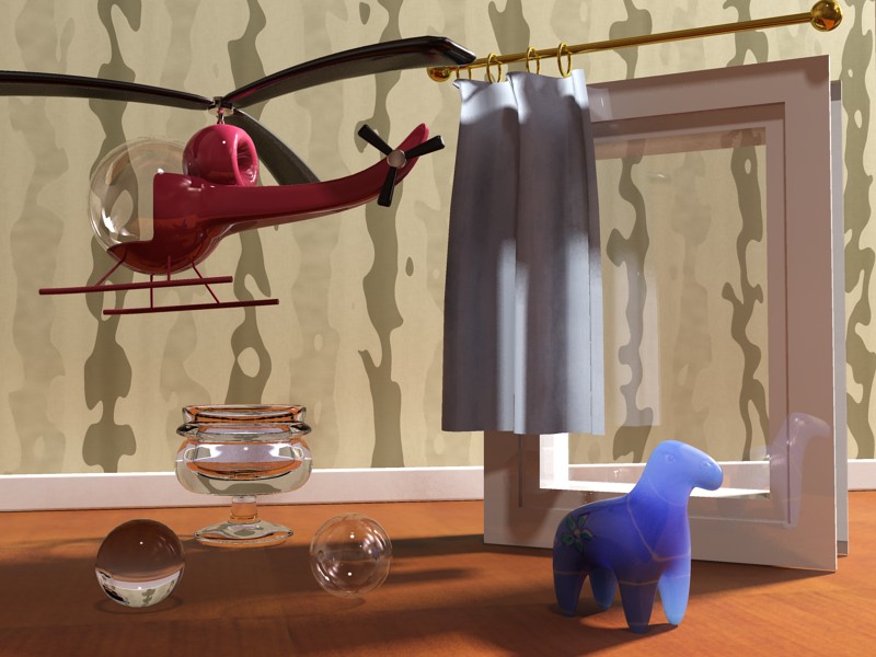
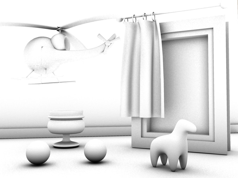
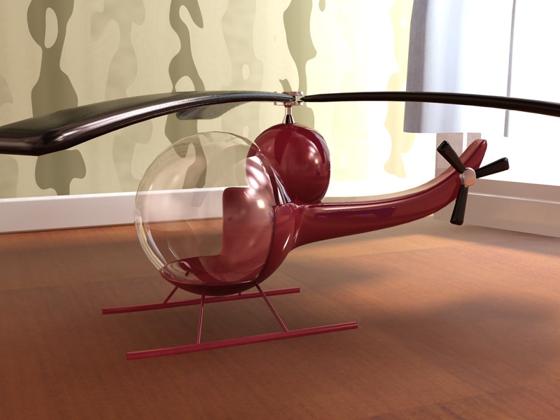
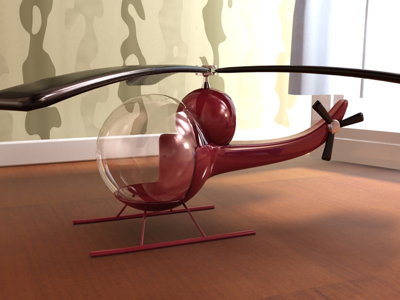
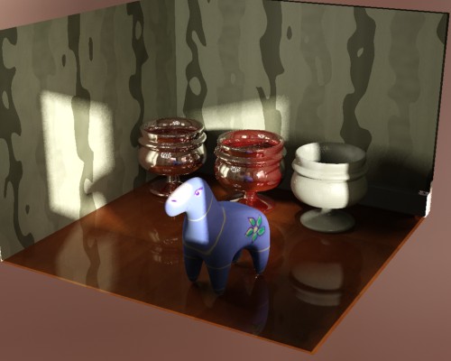
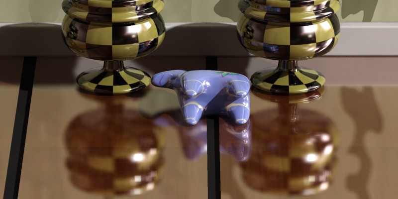
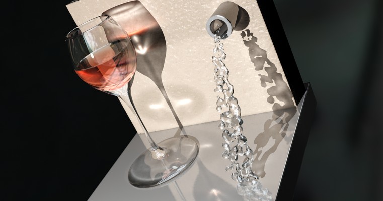
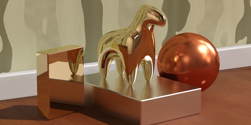
In the above image the helicopter canopy, the window pane, the translucent curtain and the right sphere all use "thin walled" transparency or translucency, whereas the glass goblet, the plastic horse and the left sphere all use "solid" transparency or translucency.
Beyond the "physical" transparency (which models an actual property of the material) there is a completely separate non-physical "cutout opacity" channel to allow "billboard" objects such as trees, or to cut out things like a chain-link fence with an opacity mask.
Ambient Occlusion (henceforth referred to as "AO") is a method spearheaded by the film industry to emulate the "look" of true global illumination by using shaders that calculate how occluded (i.e. blocked) an area is from receiving incoming light.
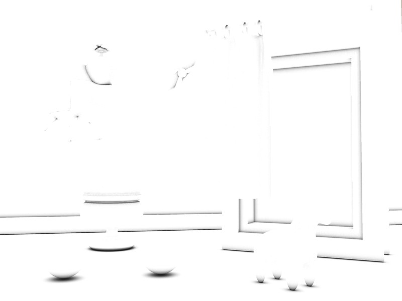
Used alone, an AO shader5 creates a gray scale output that is "dark" in areas to which light cannot reach and "bright" in areas where it can:
As seen in the above image, one of the main results of AO is dark in crevices and areas where light is blocked by other surfaces and it is bright in areas that are exposed to the environment.
One important aspect of AO is that one can tune the "distance" within which it looks for occluding geometry.
Using a radius creates only a "localized" AO effect; only surfaces that are within the given radius are actually considered occluders (which is also massively faster to render). The practical result is that the AO gives us nice "contact shadow" effects and makes small crevices visible.
There are two ways to utilize the built in AO in the
mia_material :
The latter method is especially interesting when using a highly "smoothed" indirect illumination solution (i.e. a very high photon radius, or an extremely low final gather density) which could otherwise lose small details. By applying the AO with short rays these details can be brought back.
Finally the mia_material contains a large set of built in
functions for top performance, including but not limited
to:
This section gives a quick overview of the parameters suitable
as a memory refreshing tool for users already familiar with
mia_material. A much more detailed run down is on page
Detailed
Parameters. Parameters labeled with [+] only exist in
mia_material_x.
diffuse_weight sets the desired level (and diffuse the color) of the diffuse reflectivity. Since the material is energy conserving, the actual diffuse level used depends on the reflectivity and transparency as discussed above.
The diffuse component uses the Oren-Nayar shading model. When diffuse_roughness is 0.0 this is identical to classical Lambertian shading, but with higher values the surface gets a more "powdery" look:
The reflectivity and refl_color together define level of reflections as well as the intensity of the traditional "highlight" (also known as "specular highlight").
This value is the maximum value - the actual value also depends on the angle of the surface and come from the BRDF curve. This curve (described in more detail on page Brdf) allows one to define a brdf_0_degree_refl (for surfaces facing the view) and brdf_90_degree_refl (for surfaces perpendicular to the view).
Note how the high reflectivity automatically "subtracts" from the white diffuse color. If this didn't happen, the material would become unrealistically over-bright, and would break the laws of physics 6.
The refl_gloss parameter defines the surface "glossiness", ranging from 1.0 (a perfect mirror) to 0.0 (a diffusely reflective surface):
The refl_samples parameters defines the maximum 7 number of samples (rays) are shot to create the glossy reflections. Higher values renders slower but create a smoother result. Lower values render faster but create a grainier result. Generally 32 is enough for most cases.
There are two special cases:
Metallic objects actually influence the color of their
reflection whereas other materials do not. For example, a gold bar
will have gold colored reflections, whereas a red glass orb does
not have red reflections. This is supported through the
refl_is_metal option.
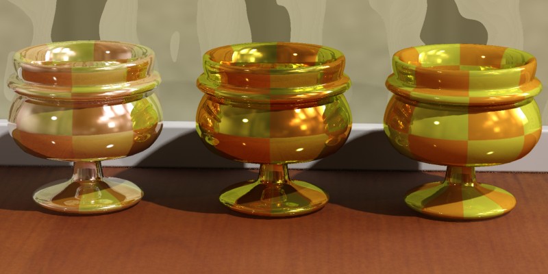
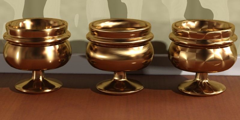
The left image shows non-metallic reflections (refl_is_metal is off). One can see reflections clearly contain the color of the objects they reflect and are not influenced by the color of the materials.
The center image uses metallic reflections (refl_is_metal is on). Now the color of reflections are influenced by the color of the material. The right image shows a variant of this with the reflectivity at 0.5, creating a 50:50 mix between colored reflections and diffuse reflections.
Glossy reflections need to trace multiple rays to yield a smooth result, which can become a performance issue. For this reason there are a couple of special features designed to enhance their performance.
The first of those features is the interpolation. By turning refl_interpolate on, a smoothing algorithm allows rays to be re-used and smoothed8. The result is faster and smoother glossy reflections at the expense of accuracy. Interpolation is explained in more detail on page Interpolation.
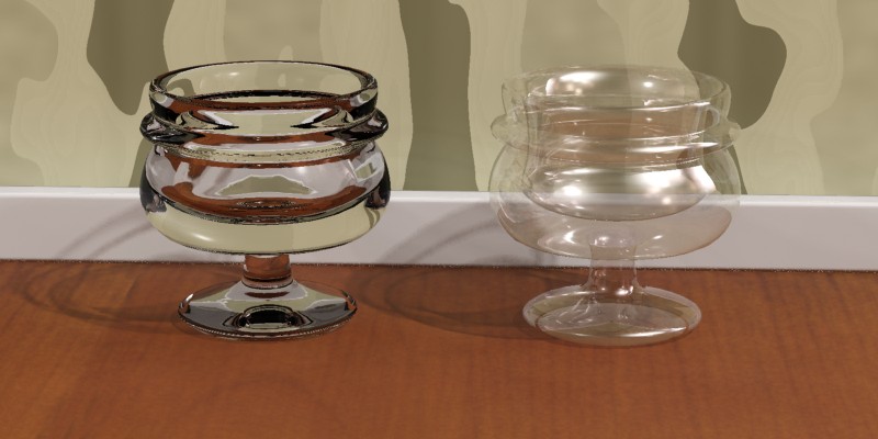
For highly reflective surfaces it is clear that true reflection rays are needed. However, for less reflective surfaces (where it is less "obvious" that the surface is really reflecting anything) there exists a performance-enhancing shortcut, the refl_hl_only switch.
When refl_hl_only is on, no actual reflection rays are traced. Instead only the "highlights" are shown, as well as soft reflections emulated with the help of using Final Gathering 9.
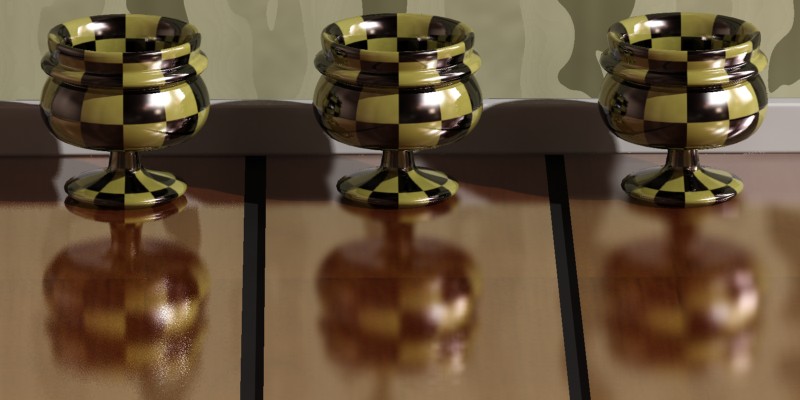
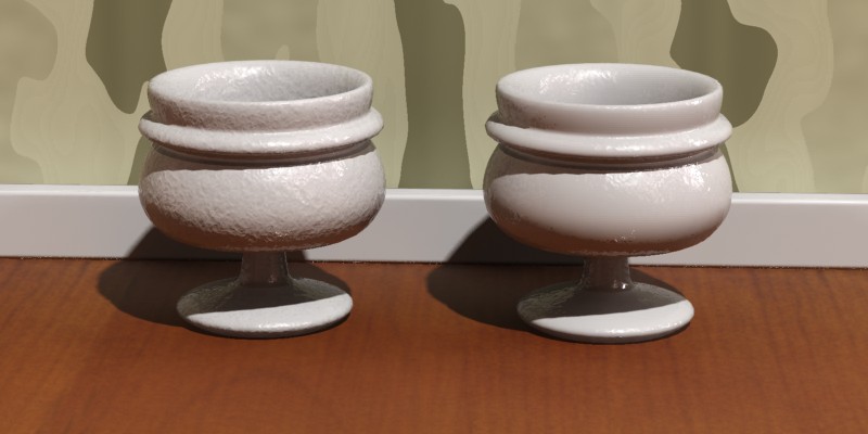
The refl_hl_only mode takes no additional render time compared to a non-glossy (diffuse) surface, yet can yield surprisingly convincing results. While it may not be completely convincing for "hero" objects in a scene it can work very well for less essential scene elements. It tends to work best on materials with weak reflections or extremely glossy (blurred) reflections:
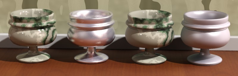
While the two cups on the left are undoubtedly more convincing than those on the right, the fact that the right hand cups have no additional render time compared to a completely non-reflective surface makes this mode very interesting. The emulated reflections still pull in a directional color bleed such that the bottom side of the cup is influenced by the color of the wooden floor just as if it was truly reflective.
The transparency parameter defines the level of refractions and refr_color defines the color. While this color can be used to create "colored glass", there is a slightly more accurate method to do this described on page Colored Glass.
Due to the materials energy conserving nature (see page Energy Conservation) the value set in the transparency parameter is the maximum value - the actual value depends on the reflectivity as well as the BRDF curve.
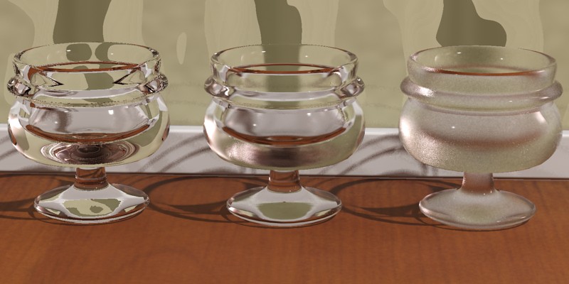
The refr_ior defines the Index of Refraction, which is a measurement of how much a ray of light "bends" when entering a material. Which direction light bends depends on if it is entering or exiting the object. The mia_material use the direction of the surface normal as the primary cue for figuring out whether it is entering or exiting. It is therefore important to model transparent refractive objects with the surface normal pointing in the proper direction.
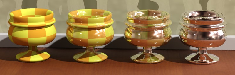
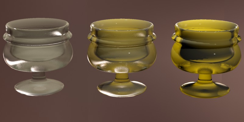
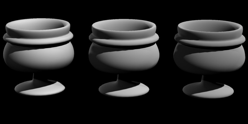
The IOR can also be used to define the BRDF curve, which is what happens in the class of transparent materials known as "dielectric" materials, and is illustrated here:
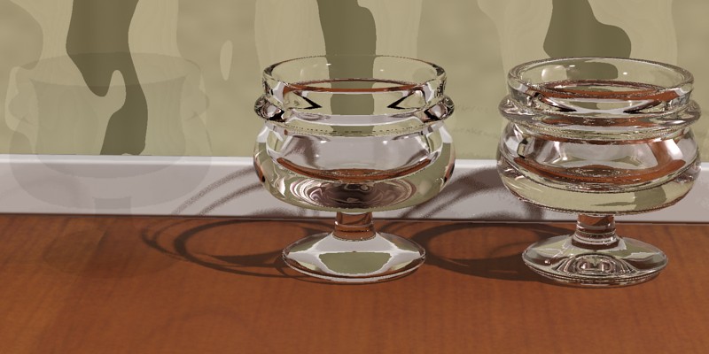
Note how the leftmost cup looks completely unrealistic and is almost invisible. Because an IOR of 1.0 (which equals that of air) is impossible, we get no change in reflectivity across the material and hence perceive no "edges" or change of any kind. Whereas the middle and rightmost cups have a realistic change in reflectivity guided by the IOR.
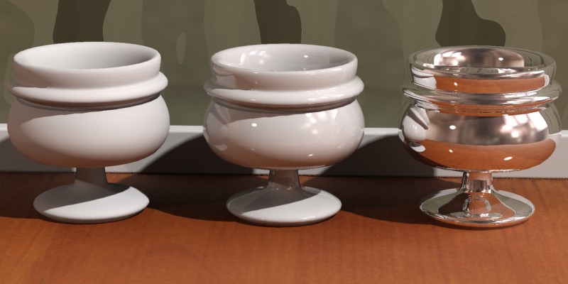
One is however not forced to base the reflectivity on the IOR but can instead use the BRDF mode to set it manually:
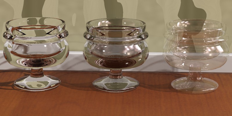
The left cup again acquires it's curve from the index of refraction. The center cup has a manually defined curve, which has been set to a brdf_90_degree_refl of 1.0 and a brdf_0_degree_refl of 0.2, which looks a bit more like metallized glass. The rightmost cup uses the same BRDF curve, but instead is set to "thin walled" transparency (see page Thin-Walled). Clearly, this method is the better way to make "non-refractive" objects compared to simply setting refr_ior to 1.0 as we tried above.
As with reflections, the refr_gloss parameter defines how sharp or blurry the refractions/transparency are, ranging from a 1.0 (a completely clear transparency) to 0.0 (an extremely diffuse transparency):
Just as with the glossy reflections, the glossy transparency has a refr_interpolate switch, allowing faster, smoother, but less accurate glossy transparency. Interpolation is described on page Interpolation.
Translucency is handled as a special case of transparency, i.e. to use translucency there must first exist some level of transparency, and the refr_trans_w parameter decides how much of this is used as transparency and how much is translucency:
The translucency is primarily intended to be used in "thin walled" mode (as in the example above) to model things like curtains, rice paper, or such effects. In "thin walled" mode it simply allows the shading of the reverse side of the object to "bleed through".
The shader also operates in "Solid" mode, but the implementation of translucency in the mia_material is a simplification concerned solely with the transport of light from the back of an object to it's front faces and is not "true" SSS (sub surface scattering). An "SSS-like" effect can be generated by using glossy transparency coupled with translucency but it is neither as fast nor as powerful as the dedicated SSS shaders.
Anisotropic reflections and refractions can be created using the anisotropy parameter. The parameter sets the ratio between the "width" and the "height" of the highlights, hence when anisotropy is 1.0 there is no anisotropy, i.e. the effect is disabled.
For other values of anisotropy (above and below 1.0 are both valid) the "shape" of the highlight (as well as the appearance of reflections) change.
The anisotropy can be rotated by using the anisotropy_rotation parameter. The value 0.0 is un-rotated, and the value 1.0 is one full revolution (i.e. 360 degrees). This is to aid using a texture map to steer the angle:
Note: When using a textured anisotropy_rotation it is important that this texture is not anti-aliased (filtered). Otherwise the anti-aliased pixels will cause local vortices in the anisotropy that appear as seam artifacts.
For values of 0 or above, the space which defines the "stretch directions" of the highlights are derived from the texture space set by anisotropy_channel 10.
anisotropy_channel can also have the following "special"
values:
state>tex prior to calling mia_materialSee also "brushed metal" on page Brushed Metals in the tips section.
As explained in the introduction on page Angle the materials reflectivity is ultimately guided by the incident angle from which it is viewed.
There are two modes to define this BRDF curve:
The first mode is "by IOR", i.e. when brdf_fresnel is on. How the reflectivity depends on the angle is then solely guided by the materials IOR. This is known as Fresnel reflections and is the behavior of most dielectric materials such as water, glass, etc.
The second mode is the manual mode, when brdf_fresnel is off. In this mode the brdf_0_degree_refl parameter defines the reflectivity for surfaces directly facing the viewer (or incident ray), and brdf_90_degree_refl defines the reflectivity of surfaces perpendicular to the viewer. The brdf_curve parameter defines the falloff of this curve.
This mode is used for most hybrid materials or for metals. Most material exhibit strong reflections at grazing angles and hence the brdf_90_degree_refl parameter can generally be kept at 1.0 (and using the reflectivity parameter to guide the overall reflectivity instead). Metals tend to be fairly uniformly reflective and the brdf_0_degree_refl value is high (0.8 to 1.0) but many other layered materials, such as linoleum, lacquered wood, etc. has lower brdf_0_degree_refl values (0.1 - 0.3).
See the tips on page Material Tips for some guidelines.
The built in Ambient Occlusion (henceforth shortened to "AO") can be used in two ways. Either it is used to enhance details and "contact shadows" in indirect illumination (in which case there must first exist some form of indirect illumination in the first place), or it is used together with a specified "ambient light" in a more traditional manner. Hence, if neither indirect light exists, nor any "ambient light" is specified, the AO will have no effect 11.
The ao_samples sets the number of samples (rays) shot for creating the AO. Higher value is smoother but slower, lower values faster but grainier. 16 is the default and 64 covers most situations.
The ao_distance parameter defines the radius within which occluding objects are found. Smaller values restrict the AO effect only to small crevices but are much faster to render. Larger values cover larger areas but render slower. The following images illustrate the raw AO contribution with two different distances:
As mentioned in the introduction on page Ambient Occlusion Effect the AO can be used for "detail enhancement" of indirect illumination. This mode is enabled by setting ao_do_details to 1.
This mode is used to apply short distance AO multiplying it with the existing indirect illumination (Final Gathering or GI/photons), bringing out small details.
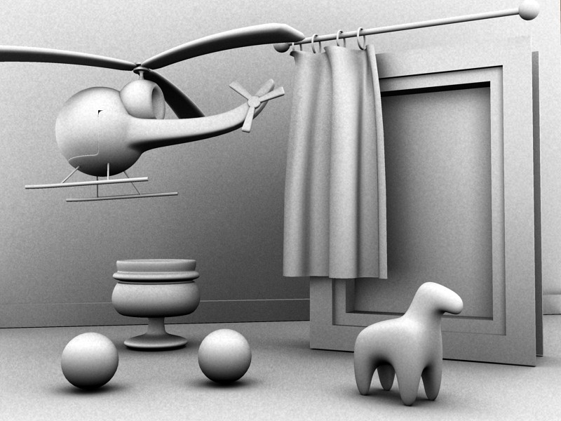
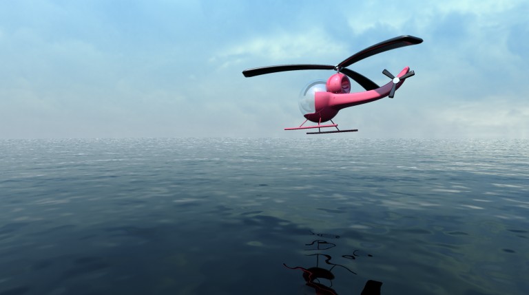
Study this helicopter almost exclusively lit by indirect light:
Note how the helicopter does not feel "grounded" in the left image and the shadows under the landing skids are far too vague. The right image uses AO to "punch out" the details and the contact shadows.
One can also set ao_do_details to 2, which enables a more sophisticated AO mode introduced in mental ray 3.6. Instead of doing simple occlusion, which can only add "darkness" of varying degree, the shader will actually look at the color of the surrounding objects, and use that color rather than "darkness". Since this involves shading each of the points hit, this is not as fast as pure AO, but it has the additional effect of resolving both bright and dark details.

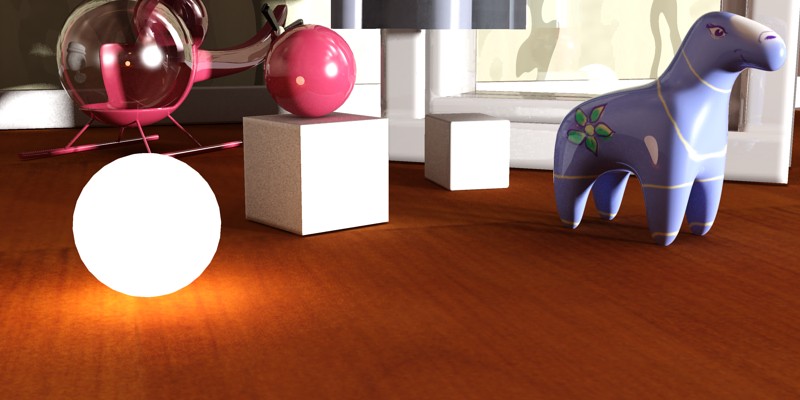
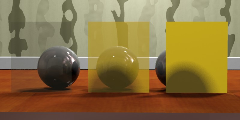
The image on the left illustrates the problem with the traditional AO; it applies to all indirect illumination and always makes it darker. It is most noticeable on the glowing sphere (which has a dark spot under it) but can also be perceived on the floor in front of the cube which is suspiciously dark, even though the cube is strongly lit on the front, as well as between the legs of the horse and the underside of the red sphere.
In contrast, the image on the right is using ao_do_details=2 for all materials, and now the floor is correctly lit by the glowing ball, there is a hint of white bounce-light on the floor from the cube, there is light between the legs of the horse, and on the underside of the red ball.
If you find that using AO creates a "dirty" look with excessive darkening in corners, or dark rims around self-illuminated objects, try to set ao_do_details to 2 for a more accurate result.
The ao_dark parameter sets the "darkness" of the AO shadows. It is used as the multiplier value for completely occluded surfaces. In practice this means: A black color will make the AO effect very dark, a middle gray color will make the effect less noticeable (brighter) etc. When the new ao_do_details mode 2 is used, it instead sets the "blend" between the color picked up from nearby objects and "darkness". The blend is:
(1-ao_dark) * (object colors) + black * ao_dark. .
The ao_ambient parameter is used for doing more "traditional" AO, i.e. supplying the imagined "ever present ambient light" that is then attenuated by the AO effect to create shadows.
While "traditional AO" is generally used when rendering without other indirect light, it can also be combined with existing indirect light. One needs to keep in mind that this magical "ever present ambient light" is inherently non-physical, but may perhaps help lighten some troublesome dark corners.
These parameters define some performance boosting options for reflections.
refl_falloff_dist allows limiting reflections to a certain distance, which both speeds up rendering as well as avoiding pulling in distant objects into extremely glossy reflections.
If refl_falloff_color is enabled and used, reflections will fade to this color. If it is not enabled, reflections will fade to the environment color. The former tends to be more useful for indoor scenes, the latter for outdoor scenes.
Each material can locally set a maximum trace depth using the refl_depth parameter. When this trace depth is reached the material will behave as if the refl_hl_only switch was enabled, i.e. only show highlights and "emulated" reflections. If refl_depth is zero, the global trace depth is used.
refl_cutoff is a threshold at which reflections are rejected (not traced). It's a relative value, i.e. the default of 0.01 means that rays that contribute less than 1 to the final pixel are ignored.
The optimization settings for refractions (transparency) are
nearly identical to those for reflections. The exception is that of
refr_falloff_color which behaves differently.
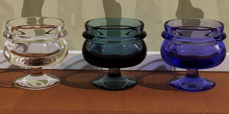
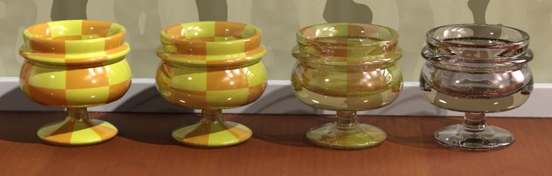
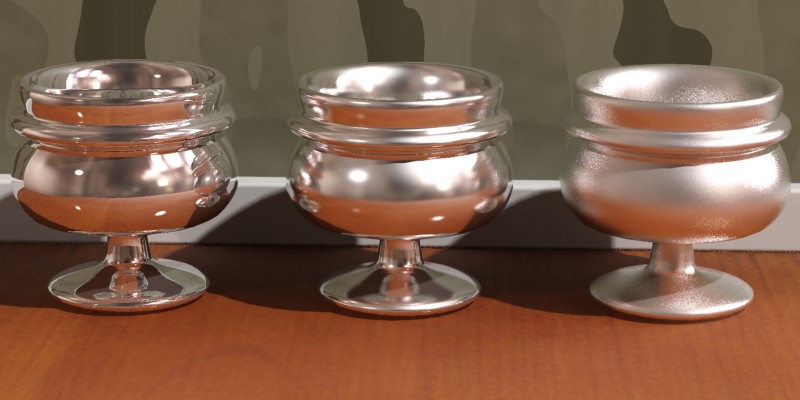
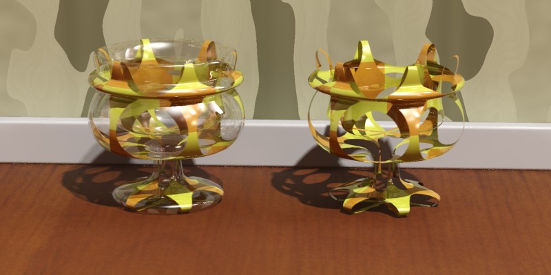
The leftmost cup has no fading. The center cup has refr_falloff_color off, and hence fades to black, which also includes the same performance benefits of limiting the trace distance as when used for reflections.
The rightmost cup, however, fades to a blue color. This causes proper exponential attenuation in the material, such that the thicker the material, the deeper the color. See page Colored Glass for a discussion about realistic colored glass.
Note: To render proper shadows when using refr_falloff_dist one must use ray traced shadows, and the shadow mode must be set to segment. See the mental ray manual on shadow modes.
Each material can locally set a maximum trace depth using the refl_depth parameter. When this trace depth is reached, the material returns a black refraction. Most other transparency/glass shaders return the environment, which can create very odd results when rendering an indoor rendering with an extremely bright outdoor environment, and bright areas appear in glass objects in dark cupboards that suddenly refract some sky. If refl_depth is zero, the global trace depth is used, and the environment is returned, rather than black.
refl_cutoff works identical to the reflection case described above.
The options contain several on/off switches that control some of the deepest details of the material:
The thin_walled decides if a material causes refractions (i.e. behaves as if it is made of a solid transparent substance) or not (i.e. behaves as if made of wafer-thin sheets of a transparent material). This topic is discussed in more detail on page Thin-Walled.
The do_refractive_caustics parameter defines how glass behaves when caustics are enabled.
When not rendering caustics, the mia_material uses a shadow shader to create transparent shadows. For objects such as window panes this is perfectly adequate, and actually creates a better result than using caustics since the direct light is allowed to pass (more or less) undisturbed through the glass into e.g. a room.
Traditionally, enabling caustics in mental ray cause all materials to stop casting transparent shadows and instead start to generate refractive caustics. In most architectural scenes this is undesirable; one may very well want a glass decoration on a table to generate caustic effect, but still want the windows of the room to let in quite normal direct light. This switch makes this possible on the material level.
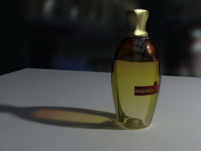
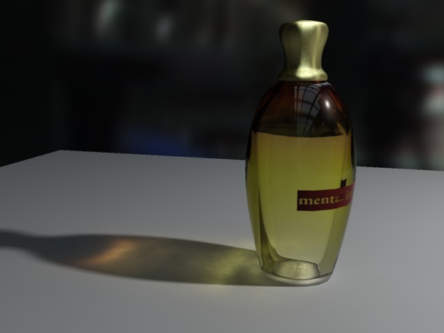
The left image shows the result that happen when do_refractive_caustics is off, the right the result when it is on. Both modes can be freely mixed within the same rendering. Photons are automatically treated accordingly by the built in photon shader, shooting straight through as direct light in the former case, and being refracted as caustics in the latter.
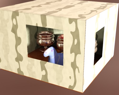
The backface_cull switch enables a special mode which makes surfaces completely invisible to the camera when seen from the reverse side. This is useful to create "magic walls" in a room. If all walls are created as planes with the normal facing inwards, the backface_cull switch allows the room to be rendered from "outside". The camera will see into the room, but the walls will still "exist" and cast shadows, bounce photons, etc. while being magically "see through" when the camera steps outside.
The propagate_alpha switch defines how transparent objects treats any alpha channel information in the background. When on, refractions and other transparency effects will propagate the alpha of the background "through" the transparent object. When off, transparent objects will have an opaque alpha.
The no_visible_area_hl parameter concerns the behavior of visible area lights.
Keep in mind that traditional "highlights" (i.e. specular effects) is a computer graphics "trick" in place of actually creating a glossy reflection of an actual visible light-emitting surface.
However, mental ray area lights can be visible, and when they are visible they will reflect in any (glossy) reflective objects. If both the reflection of the visible area light and the highlight is rendered, the light is added twice, causing an unrealistic brightening effect. This switch (which defaults to on) causes visible area lights to loose their "highlights" and instead only appear as reflections 12.
hl_vs_refl_balance modifies the balance between the intensity of the highlight and the intensity of reflections. The default value of 1.0 is the "as close to physically correct as possible" value. This parameter allows tweaking this default value where values above 1.0 makes the highlight stronger, and below 1.0 weaker.
A final optimization switch (also on by default) is the skip_inside_refl checkbox. Most reflections on the insides of transparent objects are very faint, except in the special case that occurs at certain angles known as "Total Internal Reflection" (TIR). This switch saves rendering time by ignoring the weak reflections completely but retaining the TIR's.
The indirect_multiplier allows tweaking of how strongly the material responds to indirect light, and fg_quality is a local multiplier for the number of final gather rays shot by the material. Both default to 1.0 which uses the global value.
To aid in mapping textures to fg_quality the additional fg_quality_w parameter exists. When zero, fg_quality is the raw quality setting, but for a nonzero fg_quality_w the actual quality used is the product of the two values, with a minimum of 1.0. This means that with a color texture mapped to fg_quality and fg_quality_w set to 5.0, black in the texture results in a quality of 1.0 (i.e. the number of final gather rays shot is the global default), and white in the texture in a quality of 5.0 (five times as many rays are shot).
Glossy reflections and refractions can be interpolated. This means they render faster and become smoother.
Interpolation works by pre-calculating glossy reflection in a grid across the image. The number of samples (rays) taken at each point is govern by the refl_samples or refr_samples parameters just as in the non-interpolated case. The resolution of this grid is set by the intr_grid_density parameter.
However, interpolation can cause artifacts. Since it is done on a low resolution grid, it can lose details. Since it blends neighbors of this low resolution grid it can cause over-smoothing. For this reason it is primarily useful on flat surfaces. Wavy, highly detailed surfaces, or surfaces using bump maps will not work well with interpolation. Also, since the grid exists in screen space, animations involving camera motion are not recommended since these may cause this grid-nature to become visible.
Valid values for intr_grid_density parameter are:
Within the grid data is stored and shared across the points. Lower grid resolutions is faster but lose more detail information. Both reflection and refraction has an intr_refl_samples parameter which defines how many stored grid points (in an N by N group around the currently rendered point) is looked up to smooth out the glossiness. The default is 2, and higher values will "smear" the glossiness more, but are hence prone to more oversmoothing artifacts.
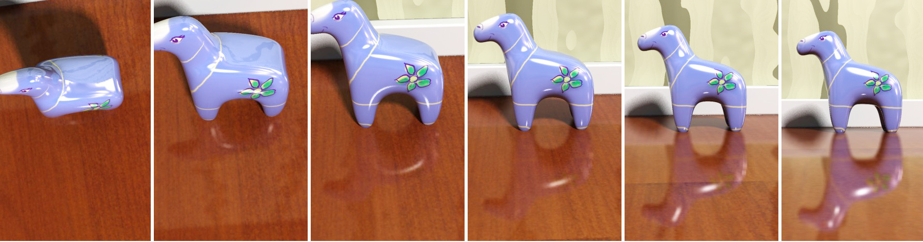
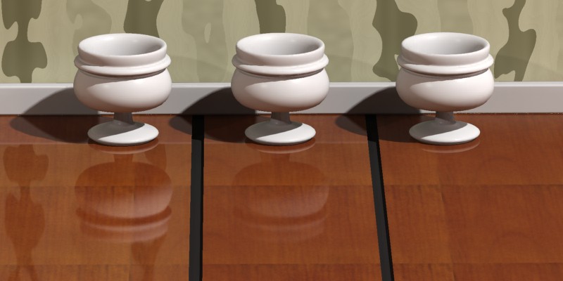
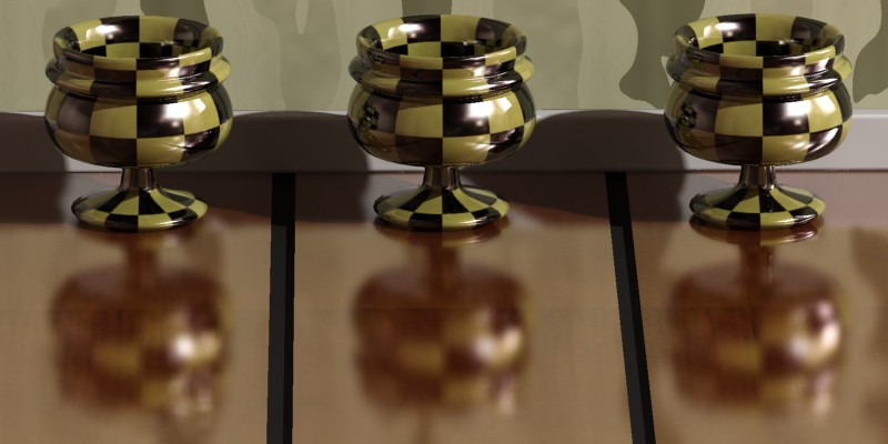
The reflection of the left cup in the floor is not using interpolation, and one can perceive some grain (here intentionally exaggerated). The floor tiles under the other two cup uses a half resolution interpolation with 2 (center) and 4 (right) point lookup respectively.
This image also illustrates one of the consequences of using interpolation: The foot of the left cup, which is near the floor, is reflected quite sharply, and only parts of the cup far from the floor are blurry. Whereas the interpolated reflections on the right cups have a certain "base level" of blurriness (due to the smoothing of interpolation) which makes even the closest parts somewhat blurry. In most scenes with weak glossy reflections this discrepancy will never be noticed, but in other cases this can make things like legs of tables and chairs feel "unconnected" with a glossy floor, if the reflectivity is high.
To solve this the intr_refl_ddist parameter exists. It allows a second set of detail rays to be traced to create a "clearer" version of objects within that radius.
All three floor tiles use interpolation but the rightmost two use different distances for the "detail distance".
This also allows an interesting "trick": Set the refl_samples to 0, which renders reflections as if they were mirror-perfect but use the interpolation to introduce blur into this "perfect" reflection (and perhaps use the intr_refl_ddist to make nearby parts less blurry). This is an extremely fast way to obtain a glossy reflection.
The above floor tiles are rendered with mirror reflections, and the "blurriness" comes solely from the interpolation. This renders as fast (or faster!) than pure mirror reflections, yet gives a satisfying illusion of true glossy reflections, especially when utilizing the intr_refl_ddist as on the right.
The mia_material also supports the following special inputs:
The bump parameter accepts a shader that perturbs the normal for bump mapping. This parameter is only used it the new bump_mode parameter is zero.
When no_diffuse_bump is off, the bumps apply to all shading components (diffuse, highlights, reflections, refractions... ). When it is on, bumps are applied to all component except the diffuse. This means bumps are seen in reflections, highlights, etc. but the diffuse shading shows no bumps. It is as if the materials diffuse surface is smooth, but covered by a bumpy lacquer coating.
In mia_material_x there are also three new parameters related to bump mapping: two vector bump inputs, overall_bump and standard_bump, and a bump_mode parameter defining the coordinate-space of those vectors. The shaders put into overall_bump or standard_bump should return a vector, but it is also legal for those shaders to modify the normal vector themselves and return (0,0,0).
overall_bump defines an overall bump that always applies both to the diffuse and the specular component at all times, regardless of the setting of no_diffuse_bump standard_bump is a vector equivalent of the old bump parameter, in that it applies globally when no_diffuse_bump is off, and only to the specular/reflection "layer" when no_diffuse_bump is on. However, the standard_bump is added "on top of" the overall_bump result.
The intended use is to put the mia_roundcorners shader in overall_bump and your normal bump shader into standard_bump. This way, the "round corners" effect will apply both to the diffuse and specular component irregardless of the setting of no_diffuse_bump.
The bump_mode parameter defines the coordinate space of the vectors, and if they are additive or not. The following values are legal:
The "add" modes mean that the vector should contain a normal perturbation, i.e. a modification that is "added" to the current normal. Whereas "set" mode means that the actual normal is replaced by the incoming vector, interpreted in the aforementioned coordinate space.
This new scheme makes the mia_material_x bump mapping compatible with more mental ray integrations, as well as allows the round corners to be applied even if no_diffuse_bump is on.
The cutout_opacity is used to apply an opacity map to completely remove parts of objects. A classic example is to map an image of a tree to a flat plane and use opacity to cut away the parts of the tree that are not there.
The additional_color is an input to which one can apply any shader. The output of this shader is simply added on top of the shading done by the mia_material and can be used both for "self illumination" type effects as well as adding whatever additional shading one may want.
The material also supports standard displacement and environment shaders. If no environment is supplied, the global camera environment is used.
Here follows a detailed listing of the available outputs of mia_material_x:
Most of the outputs follow the pattern of xxx_result, xxx_raw and xxx_level. The "result" is the final contribution, "raw" is the un-scaled contribution, and "level" is the scaling. The "level" is often related to an input parameter (or combinations thereof), and has been modified to abide by the energy conservation feature of the material.
Unless otherwise noted, it is true that Unless otherwise noted, it is true that xxx_result = xxx_raw * xxx_level. .
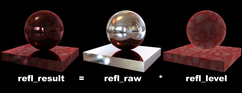
Hence the outputs contain some redundancy; if one just wants the "current reflections" in a separate channel, use refl_result, but if one wants more control over the amount of reflections in post production, one can instead use refl_raw and refl_level, multiplying them in the compositing phase prior to adding them to the final color.
Be aware, though, that mia_material_x will intentionally sample reflections that has a very low level in the actual rendering phase at low quality (for performance), so doing huge modifications to reflection intensity in post should be avoided.
The following outputs exist:
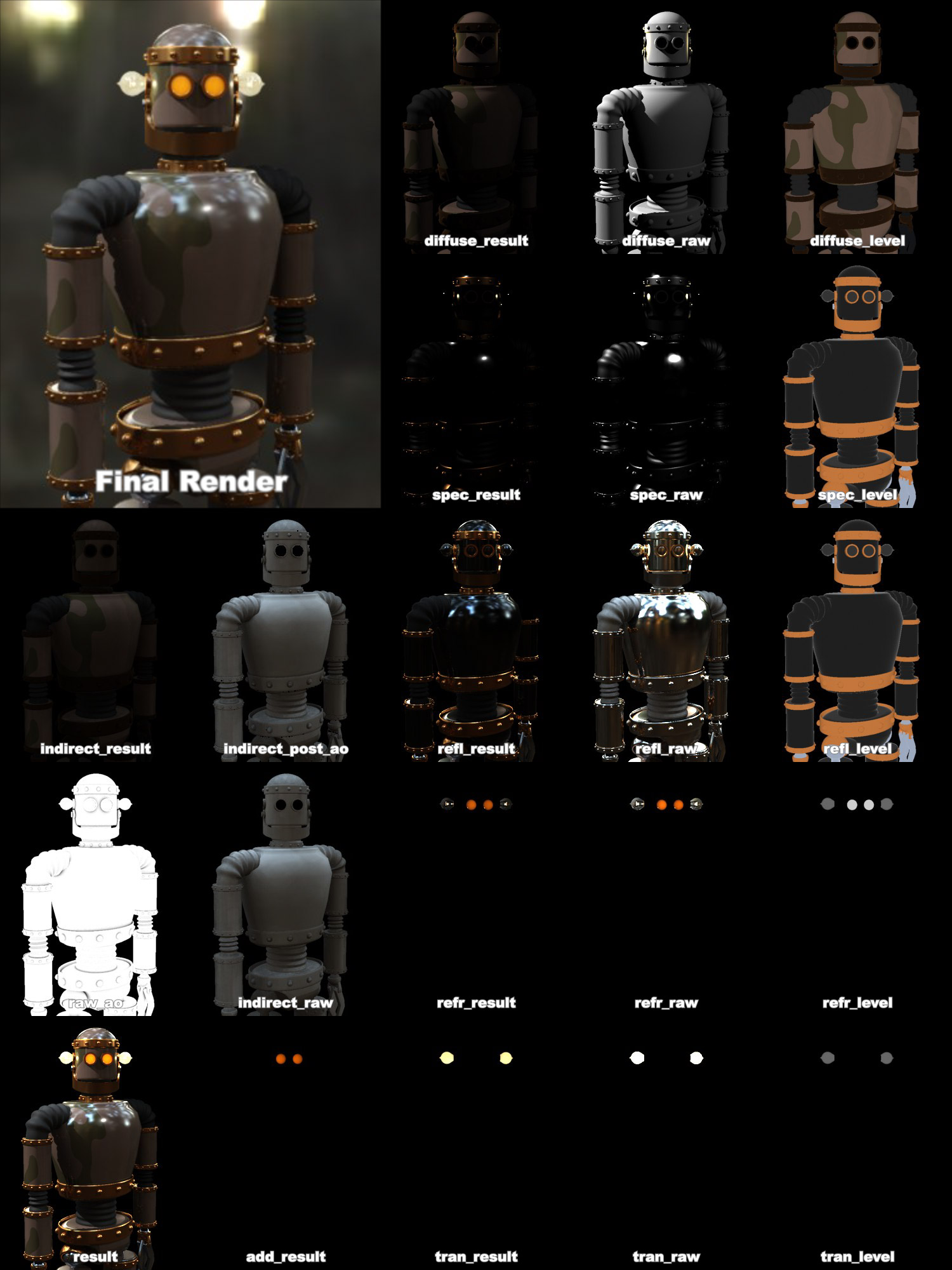
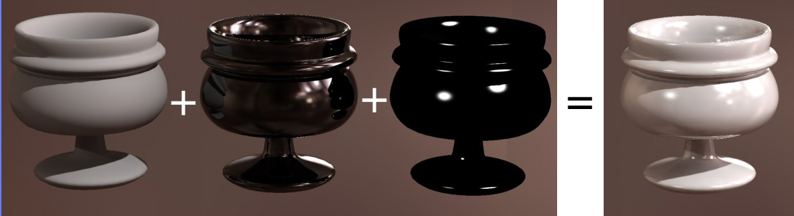
Due to the redundancy available in the outputs, there are several ways to composite them together to yield the same result as the beauty render. Here we outline two compositing pipelines in equation form.
First we have the "simple" variant, which is simply a sum of the various result parameters. This version allows only minor post production changes to the overall balance between the materials.
But it has the advantage of not needing as many files, as well as working reasonably well in non-floating-point compositing.
    Beauty = diffuse_result + indirect_result + spec_result +
                refl_result + refr_result + tran_result +
                add_result
Then we have the more "complex" variant which uses the various raw and level outputs, which allows much greater control in post production.
Note that the raw outputs needs to be stored and composited in floating point to maintain the dynamic range. The level outputs always stay in a 0.0-1.0 range and does not require floating point storage.
    Beauty = diffuse_level * (diffuse_raw + (indirect_raw * ao_raw)) +
                spec_level * spec_raw +
                refl_level * refl_raw +
                refr_level * refr_raw +
                tran_level * tran_raw +
                add_result
The Final Gathering algorithm in mental ray 3.5 is vastly improved from earlier versions, especially in it's adaptivity. This means one can often use much lower ray counts and much lower densities than in previous versions of mental ray.
Many stills can be rendered with such extreme settings as 50 rays and a density of 0.1 - if this causes "over-smoothing" artifacts, one can use the built in AO (see page Ambient Occlusion) to solve those problems.
When using Final Gathering together with GI (photons), make sure the photon solution is fairly "smooth" by rendering with Final Gathering disabled first. If the photon solution is noisy, increase the photon search radius until it "calms down", and then re-enable Final Gathering.
Here are some quick rules-of-thumb for creating various materials. They each assume basic default settings as a starting point.
This is the kind of "hybrid" materials one run into in many architectural renderings; lacquered wood, linoleum, etc.
For these materials brdf_fresnel should be off (i.e. we define a custom BRDF curve). Start out with brdf_0_degree_refl of 0.2 and brdf_90_degree_refl of 1.0 and apply some suitable texture map to the diffuse. Set reflectivity around 0.5 to 0.8.
How glossy is the material? Is reflections very clear or very
blurry? Are they Strong or Weak?
A typical wooden floor could use refl_gloss of 0.5, refl_samples of 16, reflectivity of 0.75, a nice wood texture for diffuse, perhaps a slight bump map (try the no_diffuse_bump checkbox if bumpiness should appear only in the lacquer layer).
A linoleum carpet could use the same but with a different texture and bump map, and probably with a slightly lower reflectivity and refl_gloss.
Ceramic materials are glazed, i.e. covered in a thin layer of transparent material. They follow similar rules to the general materials mentioned above, but one should have brdf_fresnel on and the refr_ior set at about 1.4 and reflectivity at 1.0.
The diffuse should be set to a suitable texture or color, i.e. white for white bathroom tiles.
Stone is usually fairly matte, or has reflections that are so blurry they are nearly diffuse. The "powdery" character of stone is simulated with the diffuse_roughness parameter - try 0.5 as a starting point. Porous stone such as bricks would have a higher value.
Stone would have a very low refl_gloss (lower than 0.25) and one can most likely use refl_hl_only to good effect for very good performance. Use a nice stone texture for diffuse, some kind of bump map, and perhaps a map that varies the refl_gloss value.
The reflectivity would be around 0.5-0.6 with brdf_fresnel off and brdf_0_degree_refl at 0.2 and brdf_90_degree_refl at 1.0
Glass is a dielectric, so brdf_fresnel should definitely be on. The IOR of glass is around 1.5. Set diffuse_weight to 0.0, reflectivity to 1.0 and transparency to 1.0. This is enough to create basic, completely clear refractive glass.
If this glass is for a window pane, set thin_walled to on. If this is a solid glass block, set thin_walled to off and consider if caustics are necessary or not, and set do_refractive_caustics accordingly.
Is the glass frosted? Set refr_gloss to a suitable value. Tune the refr_samples for good quality or use refr_interpolate for performance.
For clear glass the tips in the previous section work. But colored glass is a slightly different story.
Many shaders set the transparency at the surface of the glass. And indeed this is what happens if one simply sets a refr_color to some value, e.g. blue. For glass done with thin_walled turned on this works perfectly. But for solid glass objects this is not an accurate representation of reality.
Study the following example. It contains two glass blocks of very different size and a sphere with a spherical hole inside of it 14 plus a glass horse.
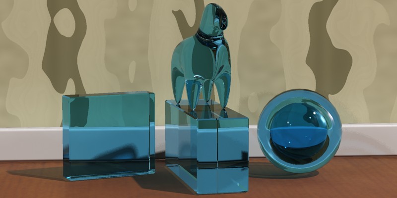
The problems are evident:
Why does this happen?
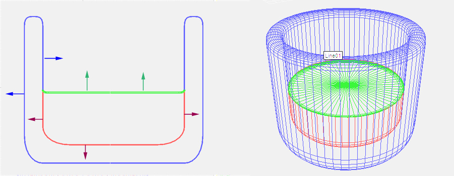
Consider a light ray that enters a glass object. If the color is "at the surface", the ray will be colored somewhat as it enters the object, retain this color through the object, and receive a second coloration (attenuation) when it exits the object:
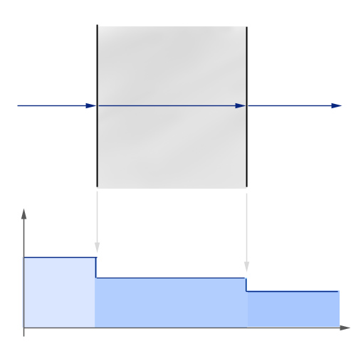
In the illustration above the ray enters from the left, and at the entry surface it drops in level and gets slightly darker (bottom of graph schematically illustrates the level). It retains this color throughout the travel through the medium and drops in level again at the exit surface.
For simple glass objects this is quite sufficient. For any glass using thin_walled it is by definition the correct thing to do, but for any complex solid it is not. It is especially wrong for negative spaces inside the glass (like the sphere in our example) because the light rays have to travel through four surfaces instead of two (getting two extra steps of "attenuation at the surface")
In real colored glass, light travels through the medium and is attenuated "as it goes". In the mia_material this is accomplished by enabling the refr_falloff_dist and use the refr_falloff_color and setting the refr_color to white. This is the result:
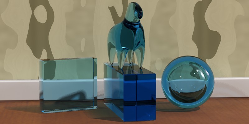
The above result is clearly much more satisfactory; the thick glass block is much deeper blue than the thin one, and the hollow sphere now looks correct. In diagram form it looks as follows:
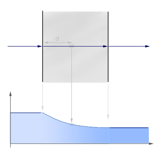
The ray enters the medium and during it's entire travel it is attenuated. The strength of the attenuation is such that precisely at the refr_falloff_dist (d in the figure) the attenuation will match that of refr_falloff_color (i.e. at this depth the attenuation is the same as was received immediately at the surface with the previous model). The falloff is exponential such that at double refr_falloff_dist the effect is that of refr_falloff_color squared, and so on.
There is one minor trade off:
To correctly render the shadows of a material using this method one must either use caustics or make sure mental ray is rendering shadows in "segment" shadow mode.
Using caustics naturally gives the most correct looking shadows (the above image was not rendered with caustics), but will require that one has caustic photons enabled and a physical light source that shoots caustic photons.
On the other hand, the mental ray "segment" shadows have a slightly lower performance than the more widely used "simple" shadow mode. But if it is not used, there shadow intensity will not take the attenuation through the media into account properly15.
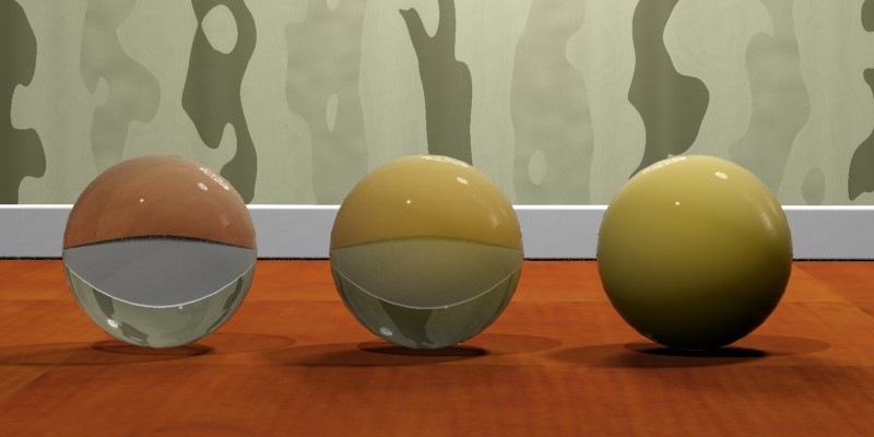
Water, like glass, is a dielectric with the IOR of 1.33. Hence, the same principles as for glass (above) applies for solid bodies of water which truly need to refract things... for example water running out of a tap. Colored beverages use the same principles as colored glass, etc.
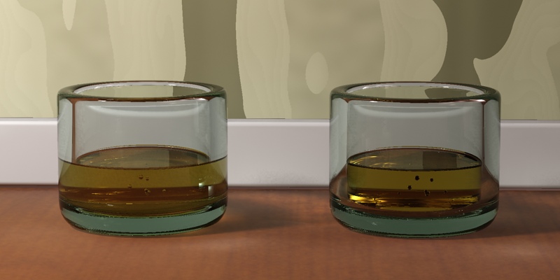
To create a beverage in a container as in the image above, it is important to understand how the mia_material handles refraction through multiple surfaces vs. how the "real world" tackles the same issue.
What is important for refraction is how the transition from one medium to another with a different IOR. Such a transition is known as an interface.
For lemonade in a glass, imagine a ray of light travelling through the air (IOR = 1.0) enter the glass, and is refracted by the IOR of the glass (1.5). After travelling through the glass the ray leaves the glass and enters the liquid, i.e. it passes an interface from one medium of IOR 1.5 to another medium of IOR 1.33.
One way to model this in computer graphics is to make the glass one separate closed surface, with the normals pointing towards the inside of the glass and an IOR of 1.5, and a second, closed surface for the beverage, with the normals pointing inwards and an IOR of 1.33, and leaving a small "air gap" between the container and the liquid.
While this "works", there is one problem with this approach: When light goes from a higher IOR to a lower there is a chance of an effect known as "Total Internal Reflection" (TIR). This is the effect one sees when diving in a swimming pool and looking up - the objects above the surface can only be seen in a small circle straight above, anything below a certain angle only shows a reflection of the pool and things below the surface. The larger the difference in the IOR of the two media, the larger is the chance of TIR.
So in our example, as the ray goes from glass (IOR=1.5) to air, there is a large chance of TIR. But in reality the ray would move from a medium of IOR=1.5 to one of IOR=1.33, which is a much smaller step with a much smaller chance of TIR. This will look different:
The result on the left is the correct result, but how it is obtained?
The solution to the problem is to rethink the modeling, and not think in terms of media, but in terms of interfaces. In our example, we have three different interfaces, where we can consider the IOR as the ratio between the IOR's of the outside and inside media:
It is evident that in the most common case of an interface with air, the IOR to use is the IOR of the media (since the IOR of air is 1.0), whereas in an interface between two different media, the situation is different.
To correctly model this scenario, we then need three surfaces, each with a separate mia_material applied:
By setting a suitable refr_falloff_dist and refr_falloff_color for the two liquid materials (to get a colored liquid), the image on the left in the comparison above is the result.
A water surface is a slightly different matter than a visibly transparent liquid.
The ocean isn't blue - it is reflective. Not much of the light that goes down under the surface of the ocean gets anywhere of interest. A little bit of it is scattered back up again doing a little bit of very literal "sub surface scattering".
To make an ocean surface with the mia_material do the following steps:
Set diffuse_weight to 0.0, reflectivity to 1.0 and transparency to 0.0 (yes, we do not use refraction at all!).
Set the refr_ior to 1.33 and brdf_fresnel to on. Apply some interesting wobbly shader to bump and our ocean is basically done!
This ocean has only reflections guided by the IOR. But this might work fine - try it. Just make sure there is something there for it to reflect! Add a sky map, objects, or a just a blue gradient background. There must be something or it will be completely black.
For a more "tropical" look, try setting diffuse to some slight greenish/blueish color, set the diffuse_weight to some fairly low number (0.1) and check the no_diffuse_bump checkbox.
Now we have a "`base color" in the water which emulates the little bit of scattering occurring in the top level of the ocean.

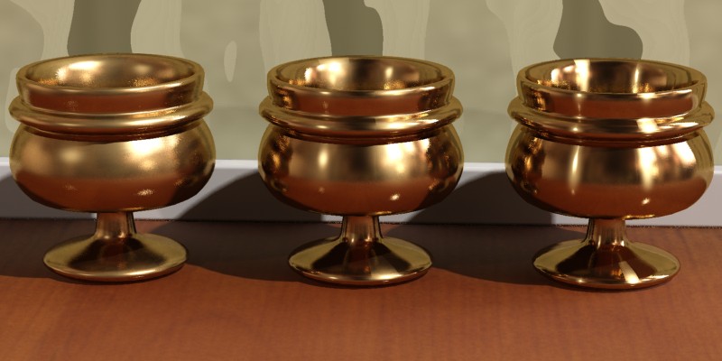
Metals are very reflective, which means they need something to reflect. The best looking metals come from having a true HDRI environment, either from a spherically mapped HDRI photo16, or something like the mental ray physical sky.
To set up classic chrome, turn brdf_fresnel off, set reflectivity to 1.0, brdf_0_degree_refl to 0.9 and brdf_90_degree_refl to 1.0. Set diffuse to white and check the refl_is_metal checkbox.
This creates an almost completely reflective material. Tweak the refl_gloss parameter for various levels of blurry reflections to taste. Also consider using the "round corners" effect, which tend to work very well on metallic objects.
Metals also influence the color of their reflections. Since we enabled refl_is_metal this is already happening; try setting the diffuse to a "gold" color to create gold.
Try various levels of refl_gloss (with the help of refl_interpolate for performance, when necessary).
One can also change the reflectivity which has a slightly different meaning when refl_is_metal is enabled; it blends between the reflections (colored by the diffuse) and normal diffuse shading. This allows a "blend" between the glossy reflections and the diffuse shading, both driven by the same color. For example, an aluminum material would need a bit of diffuse blended in, whereas chrome would not.
Brushed metal is an interesting special case of metals. In some cases, creating a brushed metal only takes turning down the refl_gloss to a level where one receives a "very blurred" reflection. This is sufficient when the brushing direction is random or the brushes are too small to be visible even as an aggregate effect.
For materials that have a clear brushing direction and/or where the actual brush strokes are visible, creating a convincing look is a slightly more involved process.
The tiny grooves in a brushed metal all work together to cause anisotropic reflections. This can be illustrated by the following schematic, which simulates the brush grooves by actually modeling many tiny adjacent cylinders, shaded with a simple Phong shader:
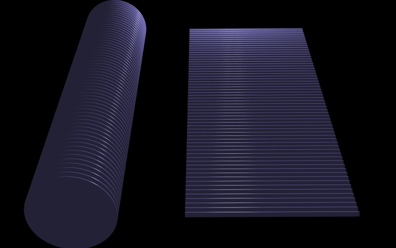
As one can see, the specular highlight in each of the cylinders work together to create an aggregate effect which is the anisotropic highlight.
Also note that the highlight isn't continuous, it is actually
broken up in small adjacent segments. I.e. the main visual cues
that a material is "brushed metal' are:
Many attempts to simulate brushed metals have only looked at the first effect, the anisotropy. Another common mistake is to think that the highlight stretches in the brushing direction. Neither is true.
Hence, to simulate brushed metals, we need to simulate these two
visual cues. The first one is simple; use anisotropy and
anisotropy_rotation to make anisotropic highlights. The
second can be done in several ways:
Each have advantages and disadvantages, but the one we will try here is the last one. The reason for choosing this method is that it works well together with interpolation.
