MatchMover provides you with a set of objects called 3D primitives. 3D primitives are basic 3D shapes such as cubes, cones or spheres. It is also possible to import an object or a scene in the OBJ format. You can use a 3D object as it appears or edit it, using one of the manipulators. The virtual objects are fixed in space, and rendered using the estimated camera parameters. The process is successful when the motion of the virtual objects in the composed sequence is consistent with that of the real scene. You can also use 3D objects to define survey points mapping by dragging the mouse from one vertex to the image plane. See Setting survey points using elastics.
Alternatively, you can select a primitive from the Toolbar by clicking on one of the primitive icons. See User Interface overview.
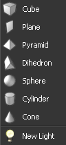
MatchMover inserts the new primitive in the scene at the origin of the coordinate system and selects it.
You can import 3D objects as files in the OBJ format. Only polygonal objects are imported. The imported objects are imported along with texture information, and can be manipulated in the same manner as the 3D primitives.
Viewing 3D primitives and objects
You can position the viewing camera to view the different faces of a 3D object or primitive by selecting View > Set 3D Viewing and one of the following options.
Deleting a 3D primitive or an object
To delete a primitive or a 3D object, do one of the following:
Editing 3D primitives and objects
You can either edit primitives in the Parameters Window or by using MatchMover’s three manipulators. See 3D primitives and objects Parameters Window.
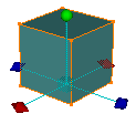
The different manipulators provide specific object manipulation possibilities, enabling you to edit any object placed within the 3D View. By default, when you create a new primitive or new light, the General manipulator surrounds the object.
The manipulator changes. Notice that the same manipulator is assigned to all new objects. Toggle between the manipulators using the Tab key.
The General manipulator allows you to carry out the following actions:
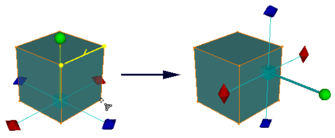
The Translate/scale manipulator
![]()
The Translate/scale manipulator allows you to carry out the following actions:
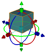
The Alignment manipulator, more complex than the other two manipulators, defines the alignment of manipulator axes and pivots.
The Alignment manipulator allows you to carry out the following actions:
Snapping the manipulator to elements
Press Shift and drag and drop a manipulator element on a vertex, an edge, or a face of the object, track points, and other primitives. The orientation axes and principal axis align an object whereas the center cube translates it.
When you place the pointer over an element, it changes to reflect the type of element you are snapping to.
 when
snapping to a vertex or a 3D Helper.
when
snapping to a vertex or a 3D Helper.
Aligning the manipulators’ pivot
MatchMover allows you to align the manipulators’ pivot with object elements.
When any of the manipulators are activated:
The following additional options apply only when the Alignment manipulator is activated:
Orientating the manipulator’s pivot
The Orient Pivot option aligns the pivot with a face of the selected object.
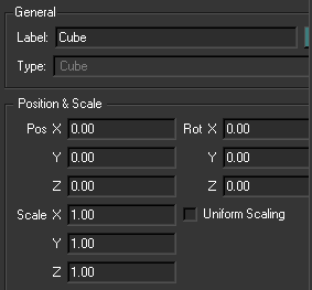
3D primitives and objects Parameters Window
You can change the name, position, rotation, scaling and color of a 3D primitive and objects in the Parameters Window.
You can stack or reposition objects by defining a plane to which a 3D object snaps.
The object snaps to the plane and the principle axis is aligned with the normal of the triangulation.
Lights are used to illuminate your scene. Lights in the 3D View are directional lights. They are created at the origin of the 3D world. By default, a diffused, ambient light illuminates the whole of the scene.
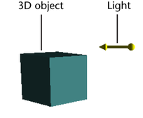
You can move lights around in the 3D View without changing the lighting; only the light orientation is important.
As soon as you insert a new light, the effects of the default lighting disappear.
To create a new light, do one of the following:
A new light appears in the 3D Scene folder of the Project window.
By default, when you place a light within a scene it is surrounded by the General manipulator. Lights are edited in the same manner as physical 3D primitives. See Editing 3D primitives and objects.
Changing the size of the non-physical objects
To change the size of any non-physical objects in a scene, for example, lights and cameras:
The 3D Icon Size is also reported in the Global Parameters Window.


 when
snapping to an edge of an object.
when
snapping to an edge of an object.
 when
snapping to a face of the object.
when
snapping to a face of the object.
 .
.
 , indicating
that you can select the vertex.
, indicating
that you can select the vertex.