The main goal of the
matchmoving is to compute both the camera motion and the scene.
If you know some of the properties of a scene, because you took
measurements, or you have some constraints, you may know the 3D
coordinates of some points of the scene. Instead of letting MatchMover
compute their 3D coordinates, you can set them before the computation.
Setting these “3D Survey points” has several advantages:
- The coordinates of the points at the
end of the computation will be exactly what you entered.
- The points help MatchMover automatically
finding the appropriate coordinate system that matches your measurements
of the scene.
- The computation will be more robust,
as all the survey points will help MatchMover finding other points
in the scene.
A minimum of four survey
points is required to define the coordinate system. You can either
set these coordinates manually or use one of your 3D object vertex
coordinates.
Setting survey points manually
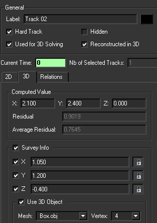
- Select
a track. The track’s properties are shown in the Parameters
Window.
- Check the Survey Info options
and either enter each known 3D coordinates directly in the corresponding
edit box or check the Use 3D Object option, then select
a 3D object in the Mesh drop-down list and a Vertex number.
You can view the vertex number by selecting Display > Mesh Vertices to
toggle the display of each vertex index of a 3D object from “none”,
through “selected vertices” to “all vertices”.
- Click the Use Object Transform checkbox
if you want to be able to alter the original shape of your object.
- Click Commit Changes to
validate.
Setting survey points using
elastics
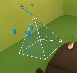
You can
create a survey point simply by using a 3D object vertex.
In a 3D
View, select the object. Drag the vertex to a position
on the background image or an existing track point to make a link.
You can then fine-tune its 2D position by clicking in the Magnifier window.
A new survey point is
created with coordinates mapped on the 3D object’s selected vertex.
The mappings can be edited in the Parameters Window.
See
Setting survey points manually.
Tip When drawing an
elastic from a large object to the image plane is complicated, you
can select the vertex you want to link and check the Use
3D Object option in the 3D tab of the
track Parameters window. The selected
vertex creates a new survey point with coordinates mapped on the
3D object’s selected vertex.