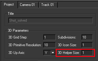
You can use the automatic tracking feature to have MatchMover select the best location of place track points in the image sequence.
The Automatic Tracking window appears listing the steps in the automatic matchmoving process.
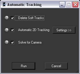
Colored indicators display beside the option name to show you the status of each step.

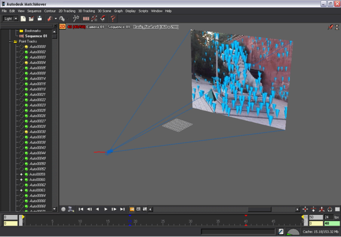
After MatchMover has computed the camera path, a collection of 3D points are displayed as cross-hairs in the Workspace. The points are also represented by colored icons in the Project window in the Point Track > Auto Tracks folders.
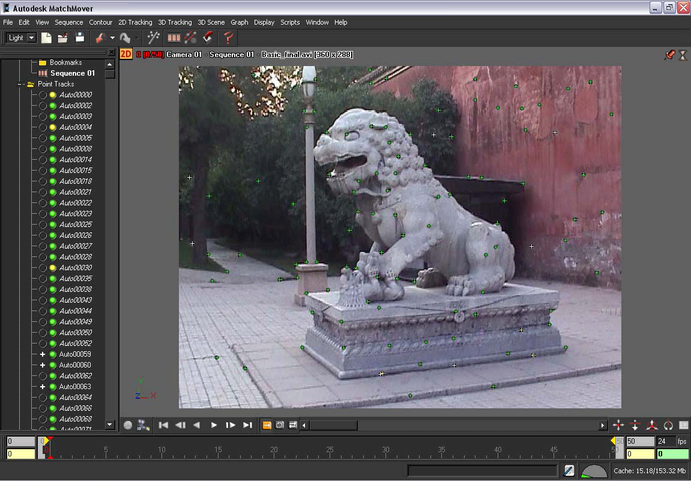
The colors indicate the quality of the tracking, where green indicates good, yellow fair, and red bad tracking. Some grayed tracks have not been reconstructed, which means that MatchMover considered them unfit to calculate.
To check the results of the automatic tracking you can:
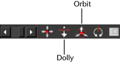
To check the tracking results in 3D space
 that
is located in the top left of the workspace view.
that
is located in the top left of the workspace view.
MatchMover switches to 3D mode. The tracks are now displayed as 3D cones rather than cross-hairs.
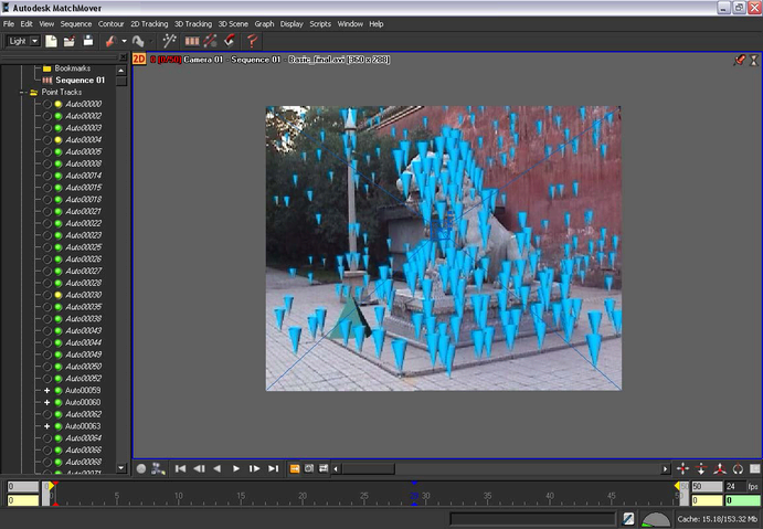
When orbiting the camera, the 3D View automatically orbits around the selected 3D object, point cloud, or camera.
When you navigate in the 3D scene, you can recognize the different elements of the scene, such as the lamppost, statue and wall, as well as the camera path.
 icon.
icon.
When viewing the Workspace, you can use of the location of the 3D cones to judge the potential orientation of any elements that you might want to introduce into the scene.